
In the previous Lesson, you learned about the Optical Sensor and the data that it reports. In this Lesson, you will learn about how to use that data in a project to move a Disk to a pallet based on the color detected. You will learn how to:
- Plan a project to sort a Disk based on the color detected by the Optical Sensor.
- Create a project to move a Disk to a pallet based on the color detected.
By the end of the Lesson, you will build on to your project to sort red and green Disks onto separate pallets based on color.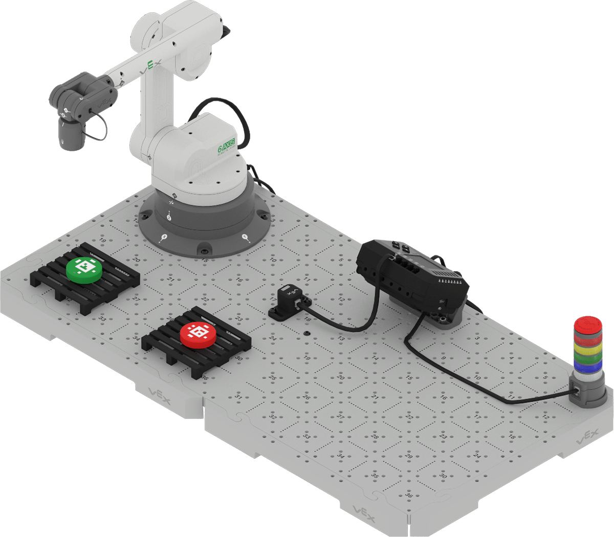
Planning a Project to Sort a Disk by Color
In the previous Lesson you learned about the Optical Sensor and how it can report the hue value and color of a detectable object. Now that you have added the Optical Sensor to your build, you are ready to use it in a project to sort Disks by color. First, you will practice planning the project, to be sure that you understand the behaviors needed to accomplish the task.
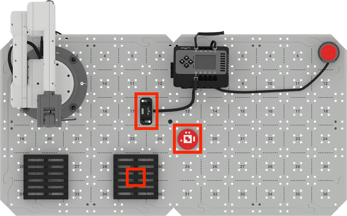
To begin, place a Disk on Brain Tile location 19, as shown in this image. This will be the loading zone for this project. Note that in this image, the pallet on the left (closer to the 6-Axis Arm) will be the green pallet, where all green Disks will be sorted. The pallet on the right (closer to the loading zone) will be the red pallet, where all red Disks will be sorted.
Note: Because the Brain CTE 6-Axis Arm Base + Optical uses two CTE Tiles, the one with the 6-Axis Arm is referred to as the "Arm Tile", and the one with the Brain is referred to as the "Brain Tile".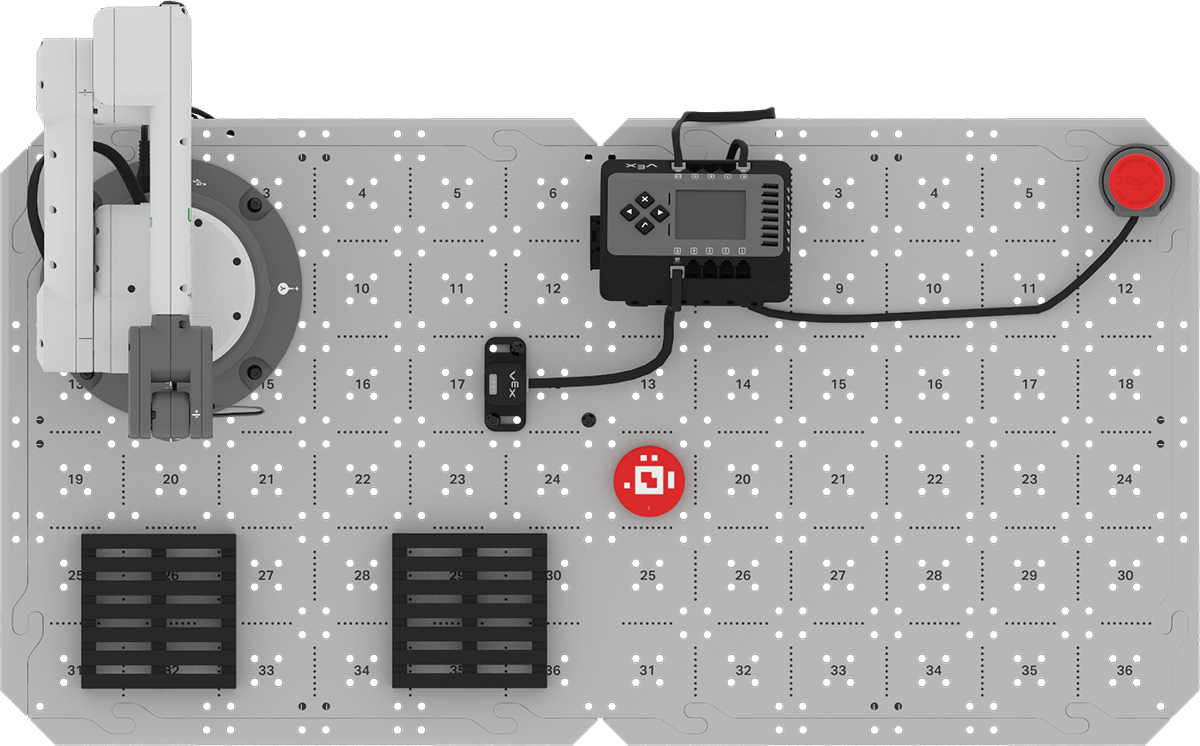
Plan the Project
You have previously made plans for moving objects from a loading zone to a pallet. Many of the same behaviors will be needed in order to sort a Disk onto a pallet by color. To accomplish this task, you will need to pick up the Disk in the loading zone, move the Disk above the Optical Sensor to detect the color, then move it to the correct pallet based on the color detected, and place the Disk onto the pallet.
We can begin with the plan to move a Disk from the loading zone to the pallet, as you recorded in your engineering notebook in Unit 1.
| Moving a Disk from the loading zone to the pallet |
| 1. Pick up a Disk |
| a. Set the 6-Axis Arm's end effector to Magnet. |
| b. Move the 6-Axis Arm to the Disk in the loading zone. |
| c. Attach the Disk to the Magnet. |
| d. Move the 6-Axis Arm above the loading zone. |
| 2. Place the Disk on the pallet |
| a. Move the 6-Axis Arm above the pallet |
| b. Move the 6-Axis Arm down to place the Disk on the pallet |
| c. Release the Disk from the Magnet. |
| d. Move the 6-Axis Arm above the pallet. |
The behaviors for picking up and placing the Disk are still the same. However, we will now need to add additional behaviors between these two steps in order to detect the color of the Disk, and move it to the correct pallet based on the color detected. This shows the plan with steps 2 and 3 added. The original step 2 has become step 4. Record the plan to sort a Disk onto a pallet based on the color detected by the Optical Sensor in your engineering notebook.
| 1. Pick up a Disk |
| a. Set the 6-Axis Arm's end effector to Magnet. |
| b. Move the 6-Axis Arm to the Disk in the loading zone. |
| c. Attach the Disk to the Magnet. |
| d. Move the 6-Axis Arm above the loading zone. |
| 2. Move the Disk over the Optical Sensor to detect the color |
| 3. Move the Disk to the correct pallet |
| 4. Place the Disk on the pallet |
| a. Move the 6-Axis Arm above the pallet |
| b. Move the 6-Axis Arm down to place the Disk on the pallet |
| c. Release the Disk from the Magnet. |
| d. Move the 6-Axis Arm above the pallet. |
Gather Coordinates with the Devices Screen
Now that you have a plan for how to sort Disks from the loading zone to the pallet based on the color detected, there are a few coordinates that you will need to know in order to build your project.
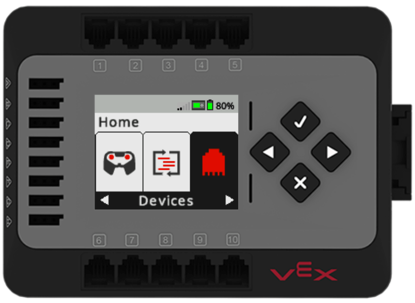
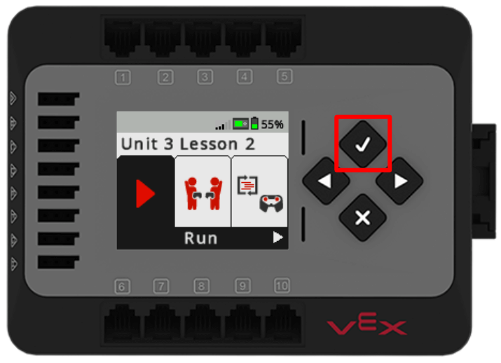
Navigate to the Devices Screen on the Brain using the Left and Right Arrow buttons. Press the Check button to open the Devices Screen.
Use the Left and Right Arrow buttons to navigate to Arm. Press the Check button to view the Arm data.
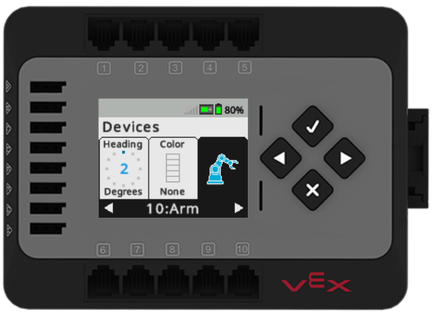
Manually move the 6-Axis Arm to the following locations, and record the coordinates in your engineering notebook:
- On top of the Disk on Brain Tile location 19 (loading zone)
- Holding the Disk over the Optical Sensor
- The center of the red pallet
For Your Information
In the previous Lesson, you tested the positioning of a Disk above the Optical Sensor as you viewed the data in the Devices Screen. As you are gathering coordinates of the location above the Optical Sensor, be mindful of the z-coordinate, to be sure that the 6-Axis Arm will hold the Disk above the Optical Sensor so that it can reliably detect and report the color. You can use the coordinates of the location above the Optical Sensor that you gathered in the Activity of the previous Lesson to use in your project.
Building and Testing the Project to Sort Disks by Color
Configure the Optical Sensor
Before you can build a project that uses the Optical Sensor, you will need to configure the Optical Sensor in VEXcode. Once the device is configured, new blocks will be added to the Toolbox, to enable you to use the Optical Sensor in a project.
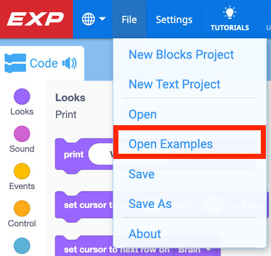
In VEXcode EXP, select Open Examples from the File menu.
Select the Brain CTE 6-Axis Arm Base template project.
Note: If opening the project for the first time, you may be prompted to allow editing permissions. Be sure to enable saving if prompted.
![]Brain CTE 6-Axis Arm Base Template project icon. The text at the bottom of the icon calls out the name of the build.](/stemlabs/sites/default/files/inline-images/Brain%20CTE%206-Axis%20Arm%20Base%20Template%20icon.png)
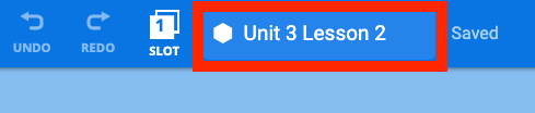
Rename the project to Unit 3 Lesson 2 and save it to your device.
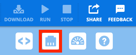
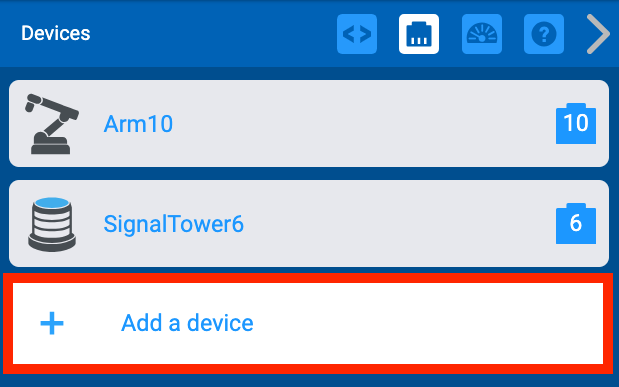
Now you are ready to configure the Optical Sensor in this project. Open the Devices Window.
Select Add a Device.
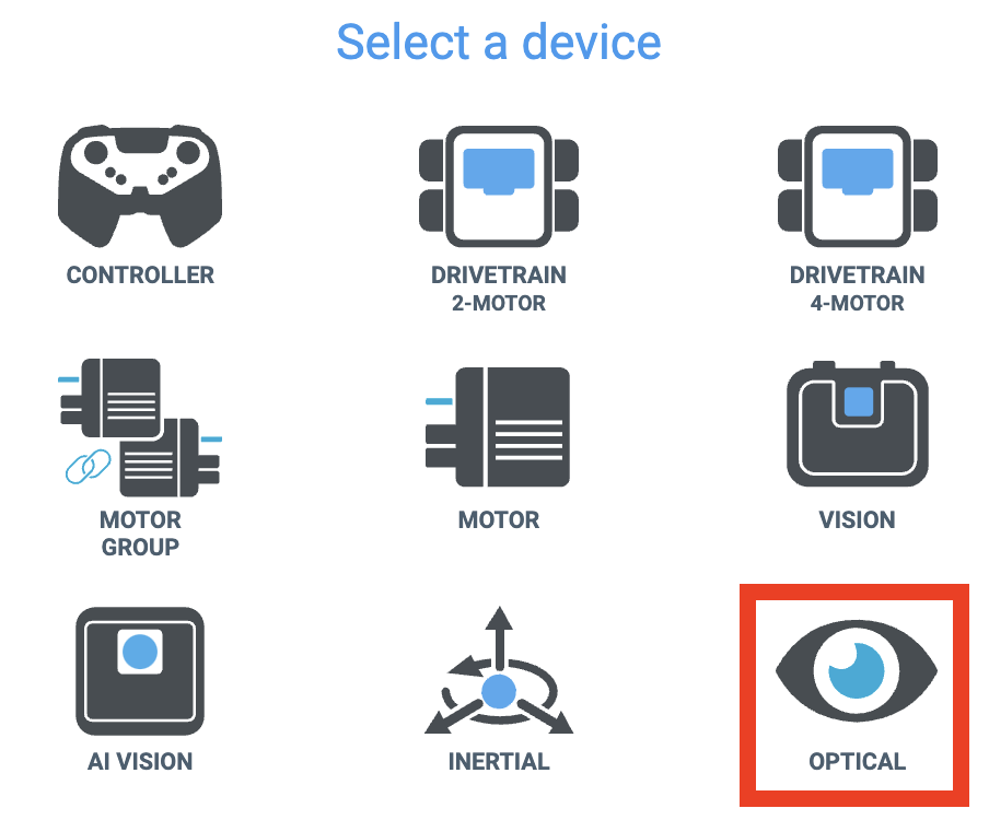
Select Optical from the list of devices.
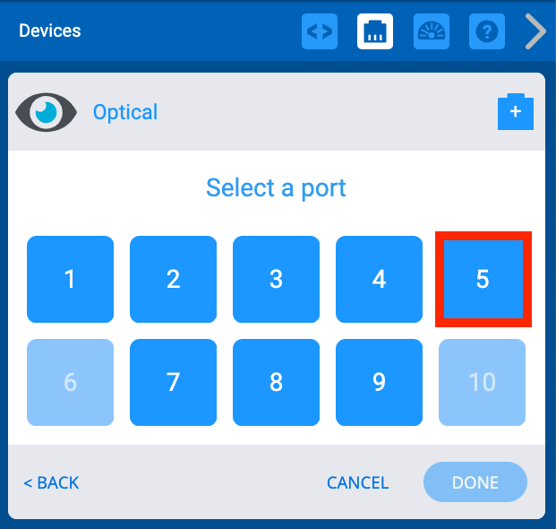
Select the port on the Brain that your Optical Sensor is plugged into.
Notice that the port number is now added to the name of the device.
Select Done to complete the configuration.
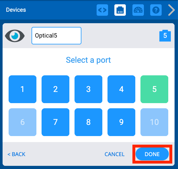
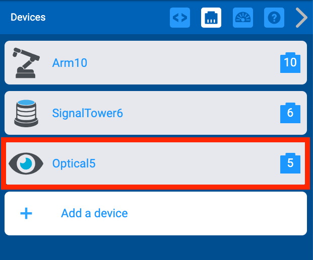
Now you will see Optical5 added to the Devices Window.
Build and Test the Project
With the Optical Sensor configured, you are now ready to begin building and testing the the project incrementally.
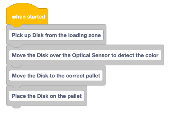
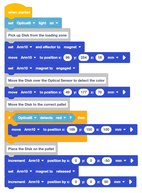
Add Comment blocks to the project for each of the steps in your plan. These should read as follows:
- Pick up Disk from the loading zone
- Move the Disk over the Optical Sensor to detect the color
- Move the Disk to the correct pallet
- Place the Disk on the pallet
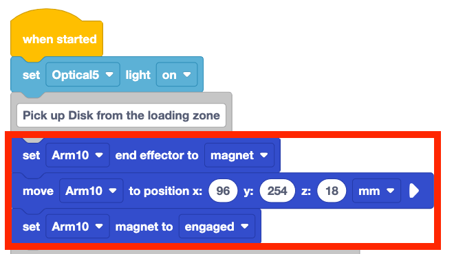
To ensure that the light on the Optical Sensor is turned on for the entire project, add a Set Optical light block to the top of the project, as shown here.
The video shows the Set Optical light block being dragged to the top of the project between the When Started block and the first Comment block.
Add the blocks needed to pick up the Disk in the loading zone.
Remember to use the coordinates you recorded in your engineering notebook, as your coordinates may differ from the example shown here.
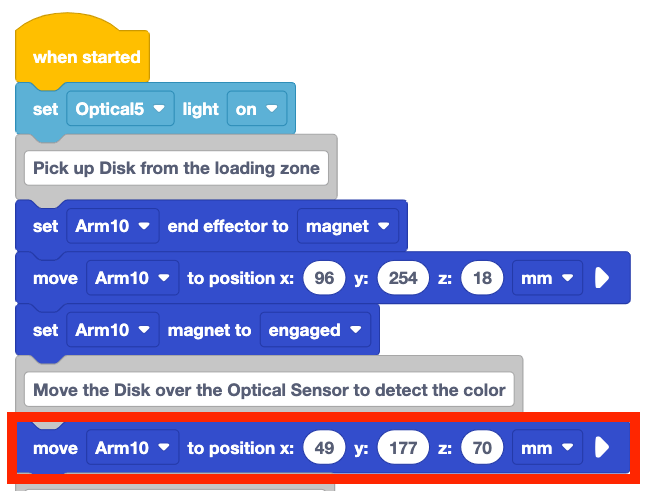
Add a Move to position block beneath the next comment. Enter the x, y, z-coordinates of the 6-Axis Arm's position above the Optical Sensor.
Be sure to use your coordinates, as they may differ from those shown in the example.
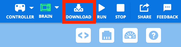
Be sure the Brain is connected to VEXcode, and download the project to the Brain.

Be sure the red Disk is placed on the loading zone, at Brain Tile location 19. Press the Check button on the Brain to run the project to test it.
Observe the behaviors of the 6-Axis Arm. Does it pick up the Disk and move it over the Optical Sensor as intended? Why or why not?
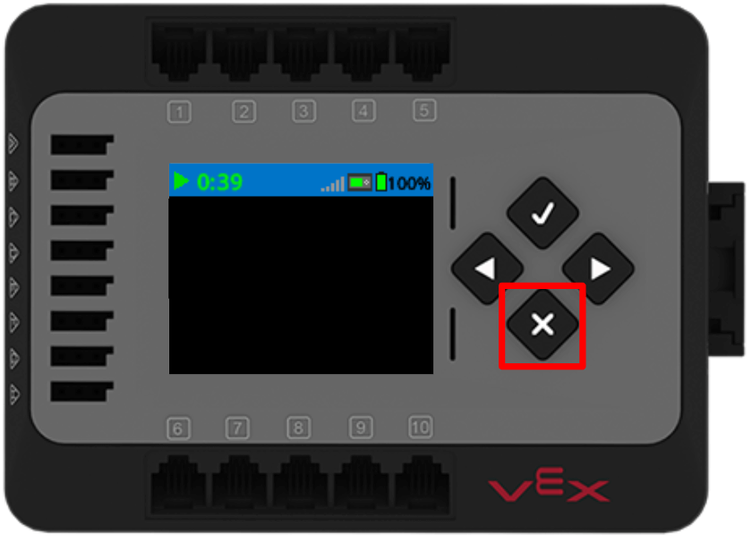
When the 6-Axis Arm has stopped moving, press the X button on the Brain to stop the project. Record your observations in your engineering notebook.
Moving the Disk to the Correct Pallet
Now that the Disk is over the Optical Sensor, data about the Disk can be used to make a decision about where to move the Disk. An If then block enables us to ask a question within a project, and use information (like the data from the Optical Sensor) to make a decision. You used If then blocks in the Introduction to the 6-Axis Arm course, when you used a variable to place Cubes into the correct positions on the pallet.
In this instance, the condition we are looking for is for the color detected by the Optical Sensor to be red. If the Optical Sensor detects red, then the 6-Axis Arm needs to move the Disk to the correct pallet.
Add an If then block to the project beneath the next comment, as shown here.
The video shows an If then block being dragged out from the Toolbox and being placed between the third and fourth comments.
Add the Optical detects color block into the hexagonal space in the If then block, as shown here.
The video shows the Optical detects color block being dragged out from the Toolbox and being placed in the hexagonal space in the top portion of the If then block. Notice that when the block is over top of the hexagonal space, a shadow appears to show that the block can be added to that space.
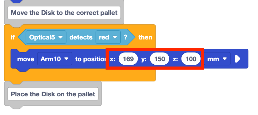
Add a Move to position block inside the C block, as shown here.
The video shows a Move to position block being dragged out from the Toolbox and being placed in the middle portion of the If then block. The If then block wraps around the Move to position block, which can be seen with the orange indentation of the If then block.
Set the x and y-parameters of the Move to position block to the x and y-coordinates of the Disk on the pallet. Leave the z-parameter set to 100, so that the 6-Axis Arm will move the Disk above the pallet location.
Be sure to use the coordinates you recorded in your engineering notebook, as they may differ from those shown in the example.
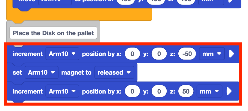
Add the blocks needed to place the Disk onto the pallet beneath the final comment, as shown here.
Read the code and predict what the 6-Axis Arm will do when the project is run.
Record your prediction in your engineering notebook.
Be sure the Brain is connected to VEXcode and download the project.
Be sure a red Disk is placed on the loading zone. Press the Check button on the Brain to run the project to test it.
Observe the behavior of the 6-Axis Arm as the project runs.

Press the X button on the Brain to stop the project when the 6-Axis Arm has finished moving. Record your observations in your engineering notebook.
Did the 6-Axis Arm move as you predicted? Did the red Disk get moved to the red pallet as intended? Why or why not?

For Your Information
If your project is not working as intended, be sure that the distance between the Disk and the Optical Sensor allows for reliable sensor data. When the project is stopped, you can use the Devices Screen to check the reported data from the Optical Sensor. Be sure that the z-value is set to position the Disk effectively over the sensor. 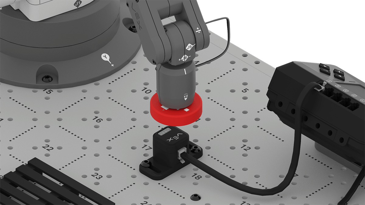 If the Disk is too high or too low in relation to the sensor, the sensor may report a hue value that does not fall within the range of what the sensor detects as 'red'. Compare the hue value to the color reported, and adjust your parameters as needed to ensure the 6-Axis Arm is positioning the Disk in an optimal location.
Reviewing the Project
Let's review the project flow in this project that moved a red Disk to the pallet. The If then block was used to make a decision based on the color detected by the Optical Sensor. The 6-Axis Arm picked up the Disk from the loading zone, then moved it above the Optical Sensor. Then a decision was made. 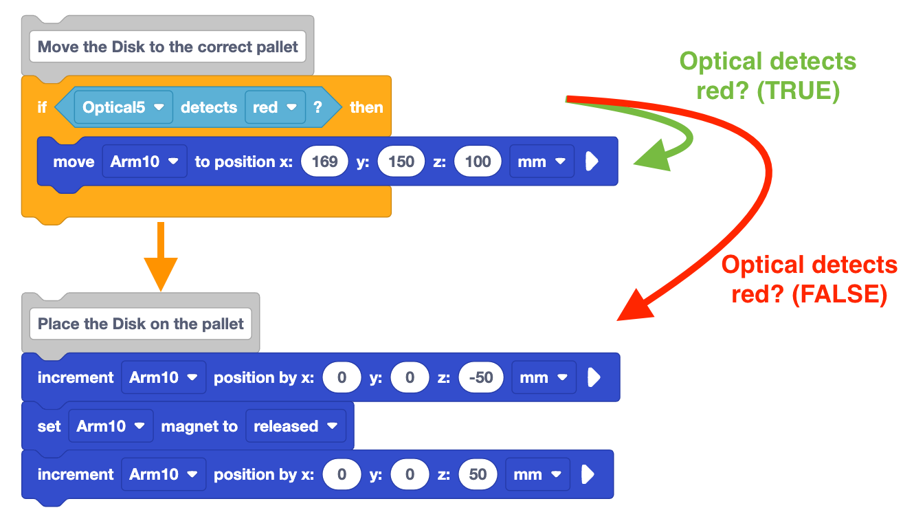
When the Optical Sensor detects red, it is reported as TRUE. Then the block inside the If then block runs, moving the red Disk to the position above the pallet. Then the rest of the project runs to place the Disk on the pallet. If the Optical Sensor did not detect red, the condition of the If then block would report as FALSE. Then the block inside the If then block would not run, and the project would move to the next blocks in the project – lowering the Disk over the Optical Sensor, instead of the pallet.
Activity
Now that you have used the Optical Sensor and the 6-Axis Arm to sort a red Disk to a pallet, you will practice these skills to sort a green Disk onto the second pallet. In this Activity, you will build onto your project from the Lesson to code the 6-Axis Arm to be able to sort a red Disk to the red pallet, and a green Disk to the green pallet. 
Activity: Create a project that will sort a red Disk onto the red pallet, and a green Disk onto the green pallet (as shown above) based on the color detected by the Optical Sensor.
- Plan how you will build onto your project to code the 6-Axis Arm to sort a green Disk to the second pallet on the CTE Workcell with your group. Be sure that you are all agreed on your approach before you begin editing the project.
- Document your plan in your engineering notebook.
- Rename your project Unit 3 Lesson 2 Activity and save it to your device before you begin editing the project.
- Edit the project in VEXcode to match the plan your group agreed upon.
- Place a Disk on the loading zone at Brain Tile location 19. Download the project to the Brain, and run it to test it. Observe the behaviors of the 6-Axis Arm as the project is running. Does the 6-Axis Arm move the Disk to the correct pallet? Stop the project when the 6-Axis Arm has finished moving. Record your observations in your engineering notebook. Do the behaviors match your plan? Why or why not?
- Run the project multiple times, and place a Disk randomly on the loading zone each time. Does the 6-Axis Arm effectively sort a red Disk to the red pallet and a green Disk to the green pallet? If not, continue to edit the project until you can successfully sort a Disk each time the project is run. Document any changes in your engineering notebook.
Check Your Understanding
Before moving on to the next Lesson, ensure that you understand the concepts in this Lesson by answering the following questions in your engineering notebook.
Check Your Understanding questions > ( Google Doc / .docx / .pdf )
Select Next > to move on to the Mid Unit Reflection.