
In the previous Lesson you learned about the components of a pneumatic system and identified those components on a real-world example. In this Lesson, you will dive further into the mechanics of a pneumatic system to understand how the compressed air moves through the system and creates motion.
In this Lesson you will learn about:
- Diagramming a pneumatic circuit
- Identifying the flow of compressed air through a pneumatic circuit
- The force created by compressed air and how it is transferred with actuations
At the end of this Lesson, you will create a diagram of the pneumatics components in a future CTE Workcell build.
Pneumatic Systems and Circuits
In previous Lessons, you learned about different pneumatic elements and identified those elements in an industrial manufacturing example. Pneumatics systems, as you have learned, capture air, transports that air through a circuit, and uses the generated energy to complete tasks. The phrase "pneumatic circuit" is used to describe one section of that system. A pneumatic circuit is a set of pneumatic components that work together to perform a single actuation (movement).
In this Lesson, you will be guided through the workings of a single pneumatic circuit.
Using Diagrams in Your Engineering Notebook
Diagrams or small sketches will be used throughout this exploration of air flow in a pneumatic circuit. These images illustrate the arrangement of individual components and describe the movement of the compressed air. Diagrams will build on one another, adding additional components as needed. Document these diagrams in your engineering notebook throughout the Lesson.
For Your Information
Diagrams can take many forms. In the CTE Digital Engineering Notebook, parts are provided to scale and can be used to diagram out pneumatic systems.
However, more simplistic drawings can also suffice to get the point across when describing the flow of air.
Use the note-taking system that best works for you in your engineering notebook.
Diagramming the Air Flow
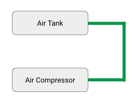
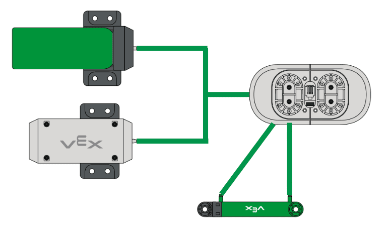
Before beginning to move the air, the air in the pneumatic circuit must be compressed. As you learned previously, this is done with an air compressor.
As the compressor creates more and more pressurized air, the air can be stored in an air tank. These components are connected with tubing.

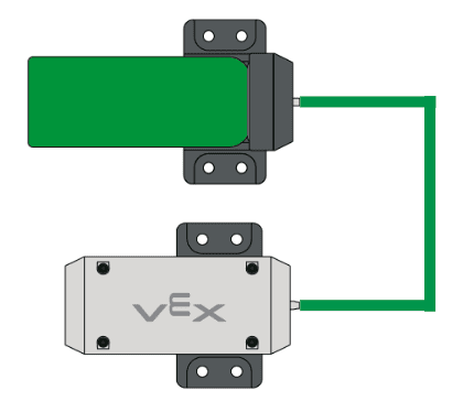
With pressurized air in the system, now the solenoid can be connected to control the flow of that air.
From the solenoid, two tubes connect to each cylinder:
- One path for the compressed air to expand the cylinder
- One path for the compressed air to retract the cylinder
For Your Information
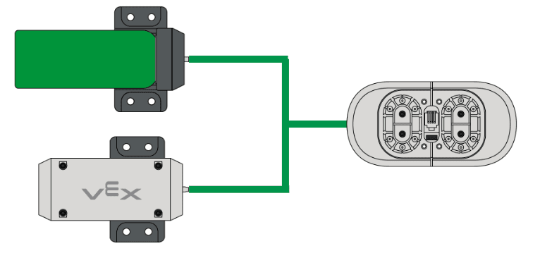
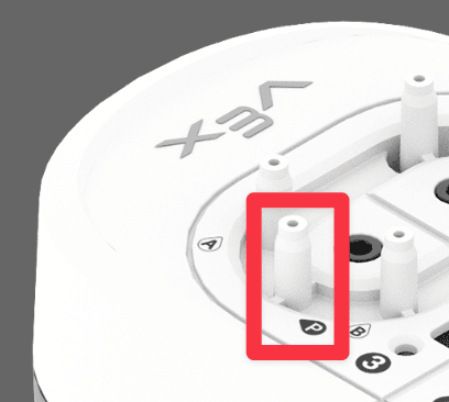
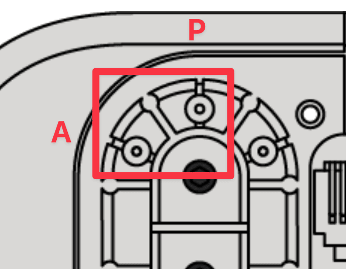
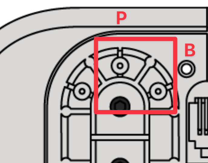
For these diagrams, the tubes are just touching the related components rather than the specific inputs and outputs that would be relevant in a build. The markings on the Pneumatic Solenoid indicate the correct placement of the tubing.
Each pneumatic circuit on the solenoid consists of three locations to connect the tubing.
- The P indicates where to connect the pressurized air from the compressor and air tank. This is the input of the solenoid.
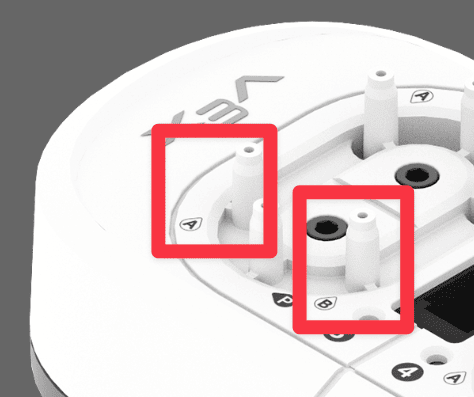
- The A indicates where to connect the tube from the A side of the Pneumatic Cylinder.
- The B indicates where to connect the tube from the B side of the Pneumatic Cylinder.
The A and B connections are the outputs of the solenoid.
These markings can be added to your diagram to better understand the inputs and outputs of the pneumatic solenoid.
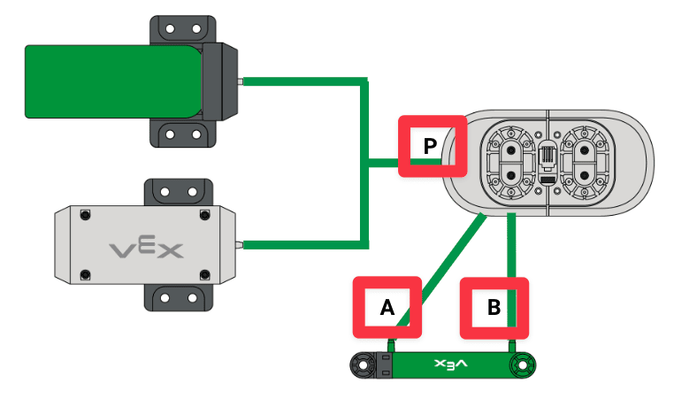
Following the Air Flow
Now that this pneumatic circuit has been diagrammed, the flow of air can be more easily seen.
Remember that compressed air is the source of energy in the pneumatic system. By following the flow of air, you can effectively follow the force as it moves through the different pneumatic components.
As previously discussed, the air is pressurized in the compressor, which begins the flow of air in the entire system.
As the air is pressurized, it will also flow into the air tank to create a store of pressurized air to be used in the event the compressor is turned off. For this example of airflow, it can be assumed that the pressurized air is coming from both the tank and the compressor.
The video to the left shows the CTE Pneumatic System with red arrows marking the airflow. The arrows follow the path of the tubing, coming out of both the tank and the compressor and flowing into the solenoid.
The compressed air is the input of the solenoid. The other tubes connected to the solenoid act as the outputs. Depending on the controls that are set, the compressed air will flow either into tube A or tube B.
The video to the left shows red arrows marking the airflow from the solenoid to the cylinder through tubes A and B.
Airflow within the Solenoid
Recall that solenoids act as a valve.
Inside of the solenoid, there is a path for the compressed air that always includes the input (P) and one output option (either A or B).
When instructed by a programmable logic controller (PLC), the solenoid will switch the airflow from one output to another. This essentially chooses whether the cylinder is set to expand or retract.
Force Inside a Pneumatic Cylinder
Once the compressed air has reached the cylinder, the air will force the piston within to either extend or retract.
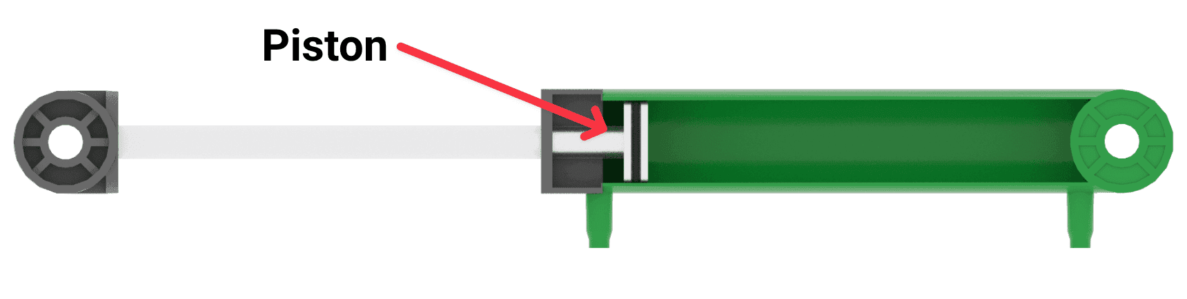
When the pressurized air pushes against the piston on the inside of the cylinder, the air exerts force on that piston to move it in a linear direction (either up and down or back and forth). The movement of that piston then is used to perform the task the system was designed for. This could include lifting, pushing, or pulling objects.
The direction of movement is based on what output is chosen on the solenoid: A or B.
When the compressed air moves through tube B to the pneumatic cylinder, the piston inside the cylinder is pushed out. This causes the end of the cylinder to expand, as shown in the video to the left.
When the compressed air moves into tube A, the piston inside the cylinder is pushed further into the cylinder. This causes the end of the cylinder to retract, as shown in the video to the left.
The force acting on the piston inside of the cylinder will cause whatever materials are attached to the piston to also move. In this video here, you can see the air flowing into the cylinder and causing the diverter to move upwards with the piston in the cylinder.
Activity
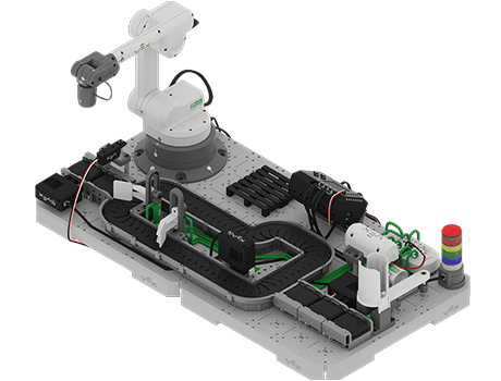
Now that you have created a diagram of a simple pneumatic circuit, you will practice your skills by creating a diagram of the pneumatic circuits that will be added to your CTE Workcell in a future Unit.
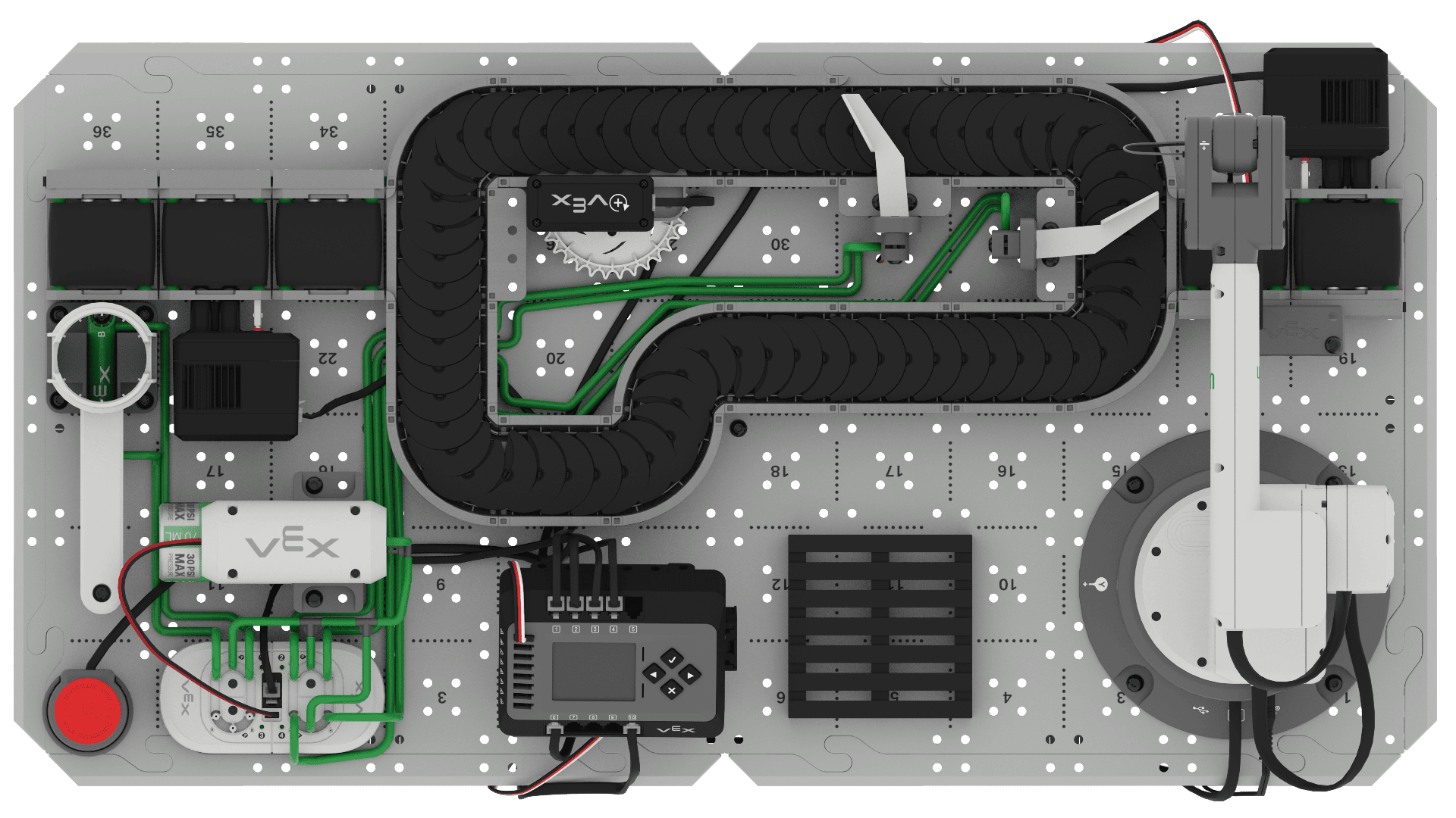
Activity: Using the image above, create a diagram in your engineering notebook of the pneumatic system.
- While creating your diagram, be sure to label each pneumatic circuit on the solenoid. Note that there are three pneumatic circuits in this build.
- You can choose whether to diagram all three circuits together or individually.
- After creating your diagram(s), answer the following questions in your engineering notebook.
- How many Pneumatic Cylinders are in this pneumatic system? What mechanisms do you think are attached to each cylinder?
- What is flow of air from the compressor to each of the cylinders? Draw the path for the air to extend each cylinder. Also draw the path for the air to retract each cylinder.
- What would you name each of these pneumatic circuits? Look at the where they are placed in the workcell and consider the function they might serve.
Check Your Understanding
Before moving on to the next Lesson, ensure that you understand the concepts in this Lesson by answering the following questions in your engineering notebook.
Check Your Understanding questions > ( Google Doc / .docx / .pdf )
Select Next > to build and test your own pneumatic circuit with the CTE Workcell Kit.