
Previously in this Unit you learned about the components of a pneumatic system and how air flows through a pneumatic circuit. Now you are ready to build your own pneumatic circuit with components from the CTE Workcell Kit, to put the concepts you've learned about into practice.
In this Lesson you will:
- Build the CTE Pneumatics Testbed
- Learn to use the Devices Screen on the Brain to control the build
- Observe the air flow of a pneumatic circuit using components from the CTE Workcell Kit
Build the CTE Pneumatic Testbed
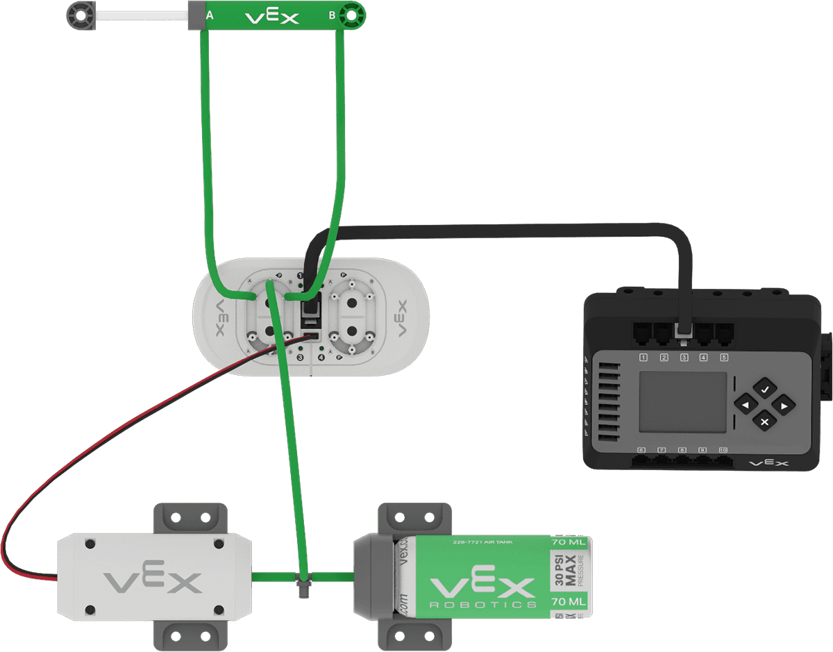
In order to explore how the air flow within a pneumatic circuit creates motion, you will use the pneumatic components from the CTE Workcell Kit to create a Pneumatic Testbed. Follow the steps below to construct the Pneumatic Testbed.
Open and follow along with the steps in the 3D Build Instructions to build the Pneumatic Testbed.
Note: While the pneumatic circuit will connect to the Brain, the components of the build will not be attached to the rest of the CTE Workcell. You can either place the Pneumatic Testbed beside your existing CTE Workcell, or detach the Brain and Battery from the build for use with the Pneumatic Testbed.

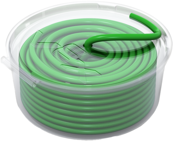
Tubing can be cut to the sizes specified in the build instructions with scissors.
Note: Be sure to keep the pieces of tubing that you cut for this build, as they will be used in the next Unit when you attach pneumatics to your CTE Workcell.
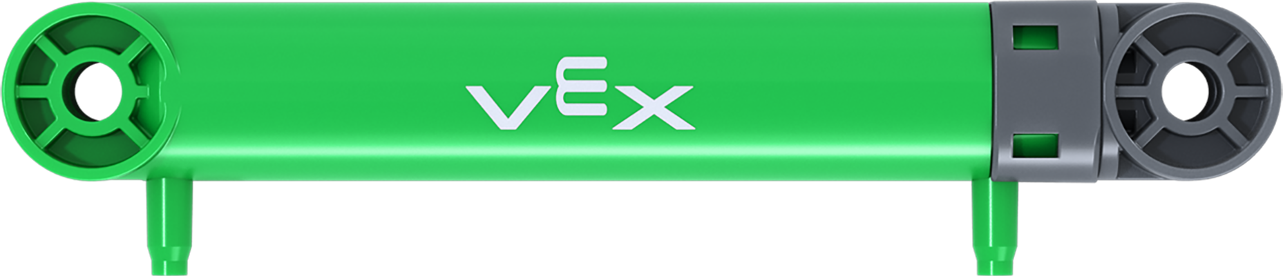
Be sure that the Pneumatic Cylinder is in the retracted position before moving on to the next steps. The default position for the Pneumatic Cylinder is retracted. The pneumatic circuit may not behave as intended if the cylinder is not retracted to begin.
Controlling the Pneumatic Testbed
In the previous Lesson you diagrammed a pneumatic circuit to investigate the air flow. Your build has the same components as your diagram, with the addition of the Brain. The Brain is the programmable logic controller, which connects to the Pneumatic Solenoid to control the direction of air flow within the circuit.
Using the Devices Screen with Pneumatics
The Devices Screen on the Brain can be used to control the Pneumatic Testbed, and make the Pneumatic Cylinder extend and retract.
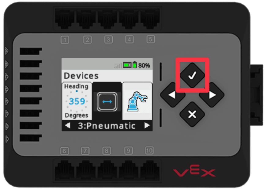
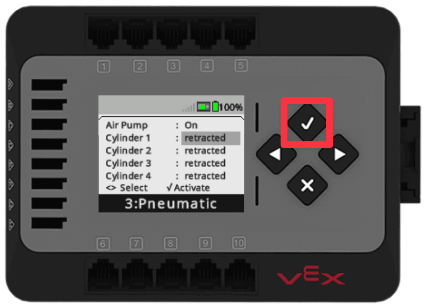
Open the Devices menu on the Brain. Press the Check to open.
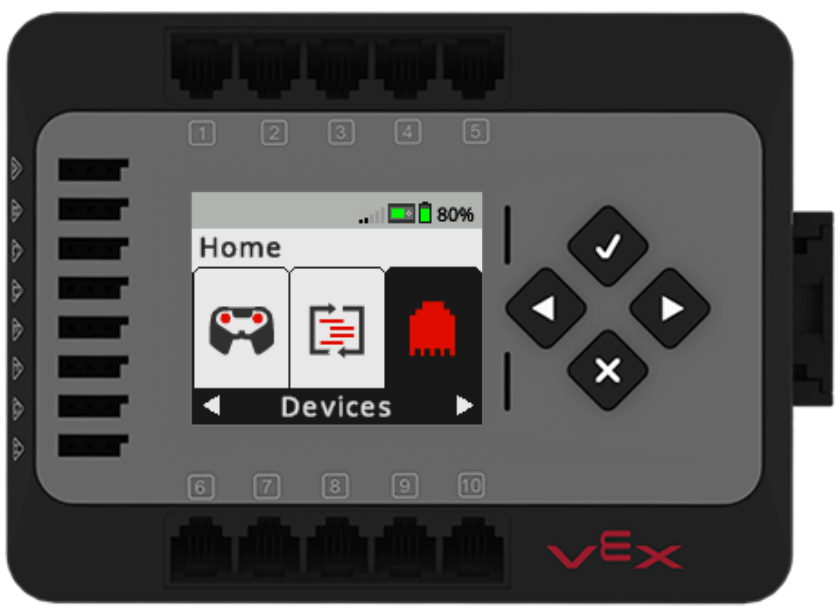
Navigate to the Pneumatic menu option. Press the Check button.
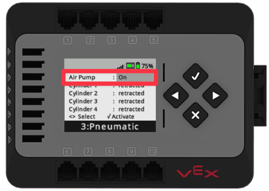
The Devices Screen will show you the current state of the pneumatic components connected to the Brain.
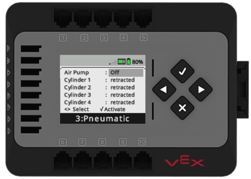
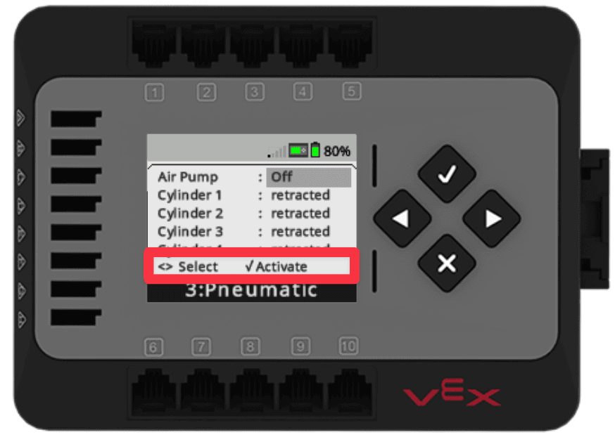
Notice that the Devices Screen indicates how the pneumatic components can be controlled using the buttons on the Brain.
- The Check button will activate a component.
- The Arrow buttons are used to select the component you wish to activate. A selected component will be highlighted.
In the image here, the Air Pump is selected. This is indicated with the gray highlight.
Controlling the Air Pump
In order for the Pneumatic Testbed to function, air must first be compressed and stored. To do this, the Air Pump must be activated. The buttons on the Brain can be used to turn the Air Pump on or off. Follow along with these steps to control the Air Pump.
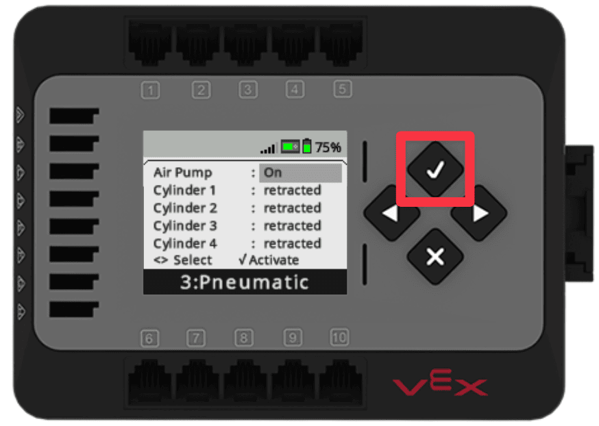
With the Air Pump status highlighted, press the Check button to turn the Air Pump on.
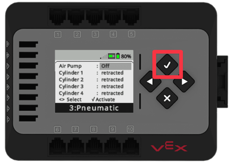
The status of the Air Pump will show as On in the Devices Screen, and you will hear the Air Pump running.
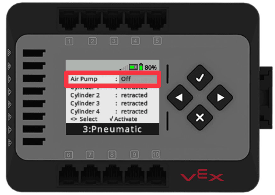
To turn off the Air Pump, press the Check button again.
The Air Pump status will now show as Off and you will hear that the Air Pump has stopped running.
Extending and Retracting the Cylinder
Now that there is compressed air in the circuit, the cylinder can be extended or retracted. Each movement of the cylinder is called an actuation. Follow these steps to extend and retract the cylinder.
Turn the Air Pump on using the buttons on the Brain.

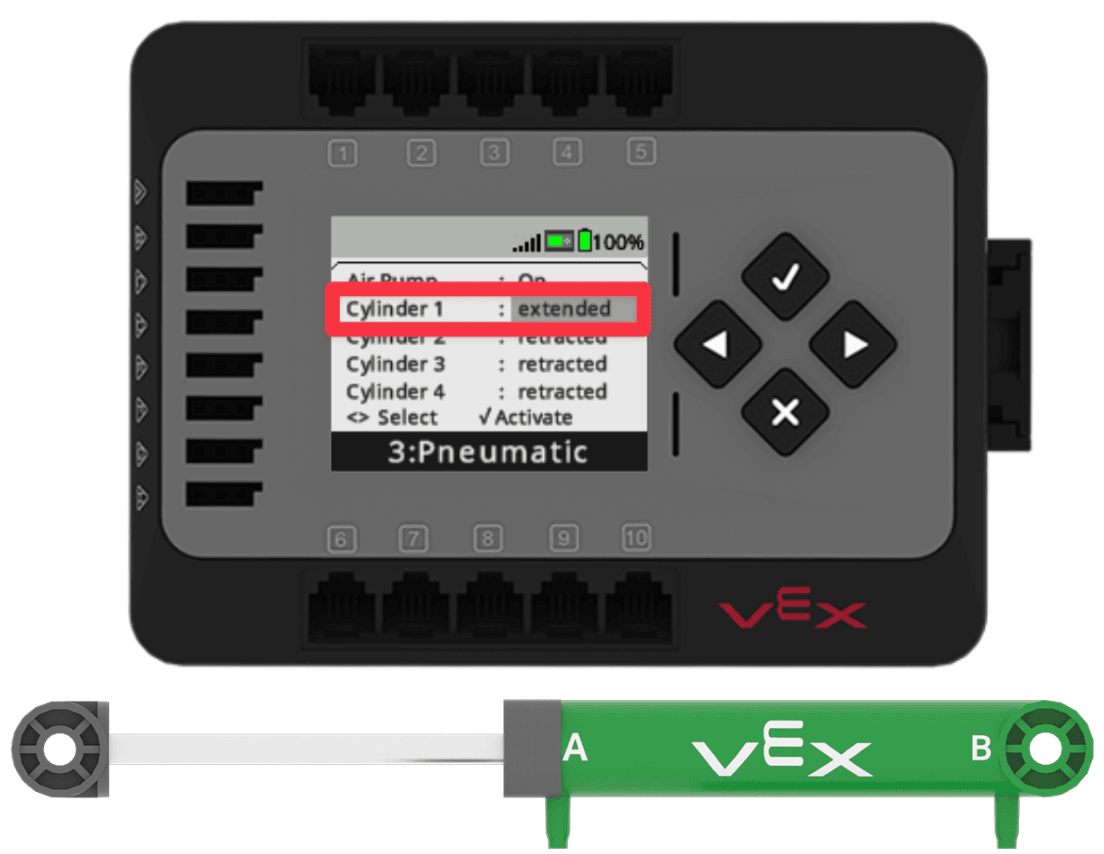
Use the Arrow button to select Cylinder 1. This is the cylinder connected to circuit 1 on the solenoid.
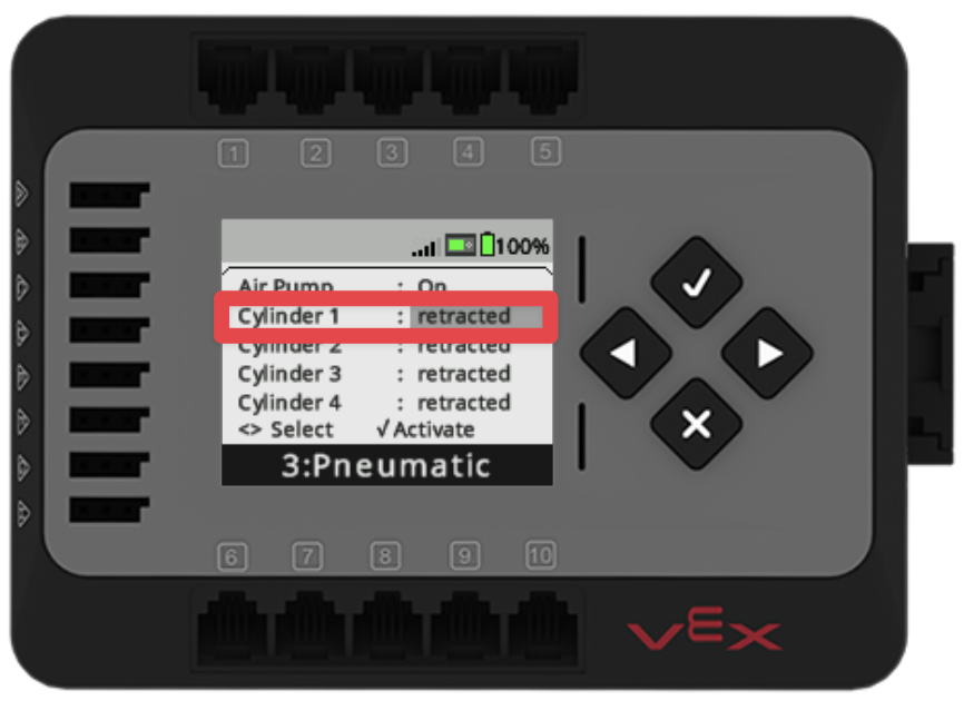
To activate the cylinder, press the Check button and observe the motion of the cylinder.
The cylinder will extend, and the status of Cylinder 1 will show as extended.
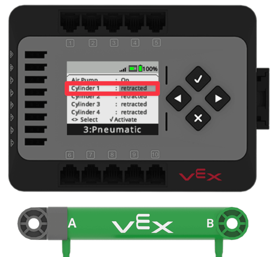
To retract the cylinder, press the Check button again. Observe the movement of the cylinder.
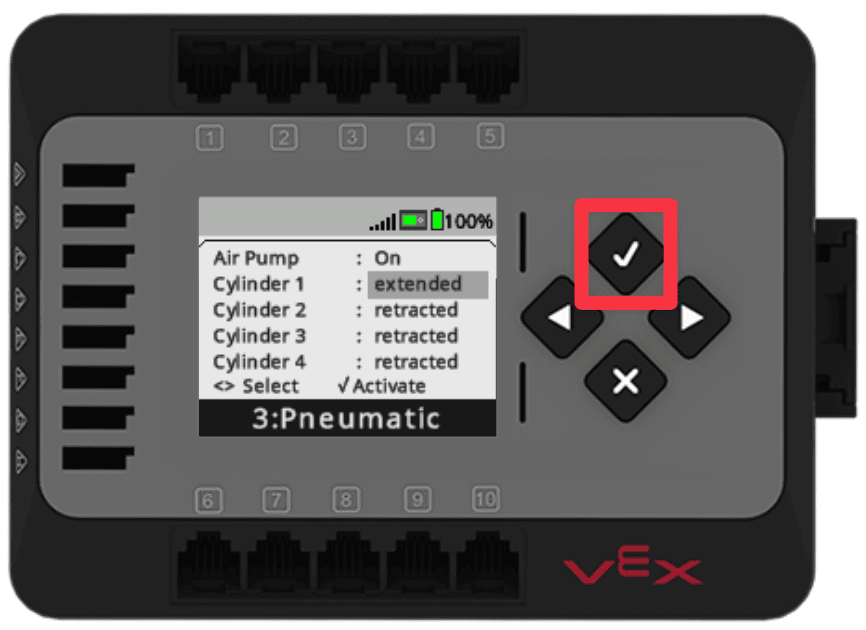
The cylinder will retract and the status of Cylinder 1 will show as retracted.
For Your Information
You may notice that Cylinders 2, 3, and 4 are listed as retracted on the Devices Screen, even though you have only connected tubing to Cylinder 1. The Devices Screen reports the status of each of the circuits on the Pneumatic Solenoid. There are always four circuits functioning within the Pneumatic Solenoid, regardless of whether or not there is tubing and Pneumatic Cylinder connected.
If you activate Cylinder 2, 3, or 4 where there is not tubing and a Pneumatic Cylinder connected, you will still see the status change on the Devices Screen. You will also hear the Pneumatic Solenoid moving to divert the air flow.
Exploring the Air Flow within the Pneumatic Testbed
Now that you know how to control the Air Pump and extend and retract the Pneumatic Cylinder, you are ready to apply what you learned about air flow to make predictions and observe the behavior of the pneumatic circuit. Follow along with the steps below as you record your observations and prediction about the Pneumatic Testbed.
Documenting the Pneumatic Testbed in Your Engineering Notebook
In the previous Lesson, you diagrammed a pneumatic circuit, like the Pneumatic Testbed that you built in this Lesson. In your engineering notebook, record what happens within the Pneumatic Testbed when you extend and retract the Pneumatic Cylinder. Answer the following questions:
- What is the air flow through the pneumatic circuit when the cylinder is retracted?
- What is the air flow through the pneumatic circuit when the cylinder is extended?
- How do the controls on the Devices Screen impact the flow of air in the solenoid?
- How does the air pressure change when the Air Pump is turned on? Turned off?
You can use words, diagrams, and/or images to document your Pneumatic Testbed. You can also continue to control the Pneumatic Testbed with the Devices Screen to help you document your build completely.
Exploring Air Flow to the Pneumatic Cylinder
Now that you have recorded how the pneumatic circuit functions to direct air flow to extend and retract the Pneumatic Cylinder, you are ready to use what you have learned to investigate air flow further. Follow along with these steps to record your predictions and observations about pneumatics.
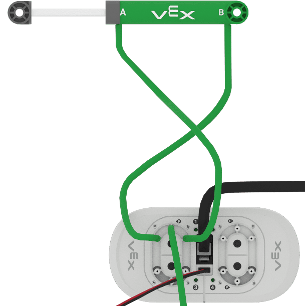
Be sure that the Air Pump is turned off. Detach the Tubing from the A and B sides of the Pneumatic Cylinder and reattach them in the opposite orientation, as shown here.
The tube that was connected to A, should get reconnected to B. The tube that was connected to B, should get reconnected to A.
Note: You may hear the pressurized air release when the tubing is disconnected. This is expected if there is pressurized air in the system.
2. Predict what you think will happen when you set Cylinder 1 to extend in the Devices Screen on the Brain.
- Record your prediction about the air flow and the movement of the Pneumatic Cylinder in your engineering notebook.
3. Turn on the Air Pump and use the Devices Screen to activate Cylinder 1 to change it from extended to retracted multiple times.
- Observe the movement of the Pneumatic Cylinder. Does it match your prediction? Why or why not.
- Record your observations in your engineering notebook.
Exploring the Air Tank and Air Pump
The Air Pump and Air Tank work together to take in air and store it for use in the pneumatic circuit. The Pneumatic Cylinder can only extend and retract if there is sufficient compressed air within the system. Follow along with these steps to record your predictions and observations about using the Air Tank and Air Pump.
Be sure the Pneumatic Cylinder is in the retracted position to begin. Turn the Air Pump on and run it for 1-2 minutes to collect air in the Air Tank.

5. Turn the Air Pump off. Predict what you think will happen as you move the Pneumatic Cylinder without turning the Air Pump on again.
- How many times will the cylinder be able to extend and retract? What do you think will happen to the movement of the Pneumatic Cylinder as the air is used?
- Record your predictions in your engineering notebook.
6. Using the Devices Screen, activate Cylinder 1 to extend and retract the Pneumatic Cylinder as many times as you can. Observe the movement of the Pneumatic Cylinder.
- How many actuations (extensions/retractions) can be completed before the Pneumatic Cylinder does not move? What happens to the movement of the Pneumatic Cylinder as there is less air in the Air Tank? Why do you think that is?
- Record your observations in your engineering notebook.
Check Your Understanding
Before moving on to the next Unit, ensure that you understand the concepts in this Lesson by answering the following questions in your engineering notebook.
Check Your Understanding questions > ( Google Doc / .docx / .pdf )
Wrap Up Reflection
Now that you have built and tested the CTE Pneumatic Testbed, it is time to reflect on what you have learned and done in this Unit.
Rate yourself as a novice, apprentice, or expert on each of the following concepts in your engineering notebook. Provide a brief explanation for why you gave yourself that rating for each concept:
- Describing the advantages of pneumatics in industry
- Identifying the components of a pneumatics system
- Describing the air flow of a pneumatic circuit
Use this table to help you determine which category you fall under.
| Expert | I feel that I fully understood the concept and could teach this to someone else. |
| Apprentice | I feel that I understood the concept enough to complete the activity. |
| Novice | I feel that I did not understand the concept and do not know how to complete the activity. |
Then, reflect on the learning targets you co-created with your teacher for this Unit. Have you learned what you set out to learn? Why or why not? What were you most successful with? Why? How do you think you can build on your progress moving forward?
Each person in your group should complete their self-reflections in their engineering notebooks. Once everyone in your group has completed their self-reflections, check-in with your teacher and let them know you are ready for your debrief conversation.
Debrief Conversation
Using your reflections and notes in your engineering notebook, rate yourself on the Debrief Conversation Rubric (Google Doc / .docx / .pdf ). For each of the topics, rate yourself as Expert, Apprentice, or Novice.
Ask your instructor if you need any clarification on what is expected of your during this self assessment.

Select < Return to Units to go back to all Units.