
In the previous Lesson, you learned about how and why pneumatics are used in industrial manufacturing. In this Lesson, you will learn:
- What the components of a pneumatic system are
- What each component does within the system
By the end of this Lesson, you will be able to describe the pneumatic components and motion you see in a video of an industrial manufacturing process.
The Components of a Pneumatic System
Pneumatic systems are often designed to meet the needs of a particular manufacturing environment, so there are many variations on how they are configured. However, pneumatic systems typically include the following components:
- Air compressor
- Air tank
- Tubing
- Solenoid
- Actuator
Air Compressor
An air compressor provides the force in a pneumatic system. It converts power from an engine or motor into potential energy stored as pressurized, or compressed, air.
The compressor draws in air from the atmosphere, and then compresses the air to a higher pressure by mechanically reducing its volume.
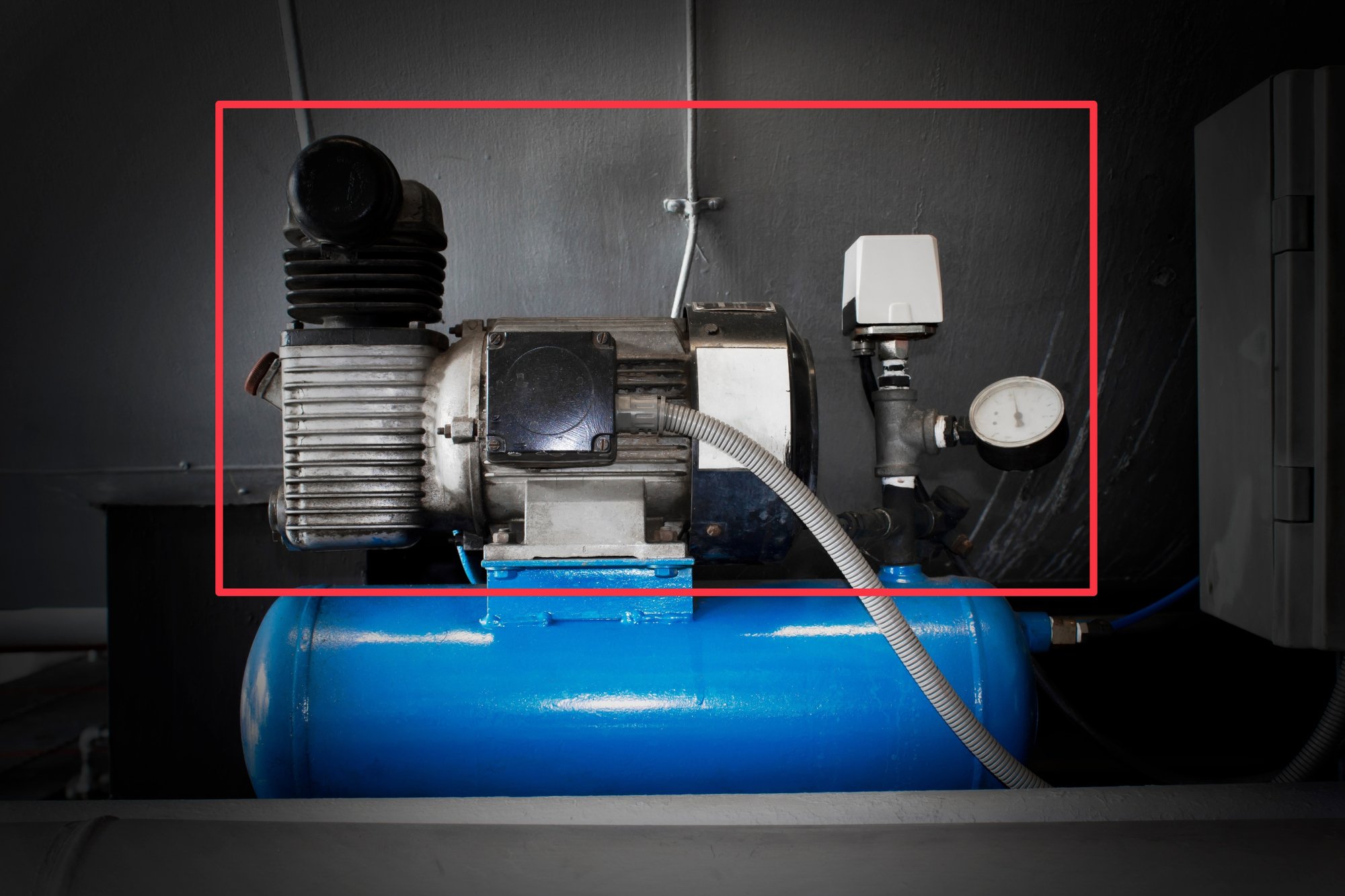
In the CTE Workcell Kit, the compressor is called the Air Pump.
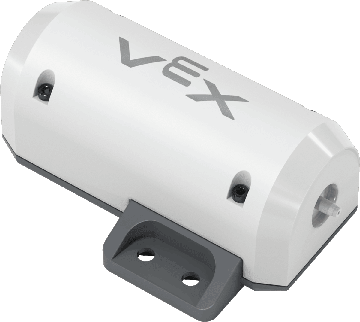
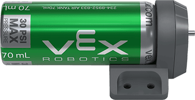
Air Tank
The air tank holds the pressurized air from the compressor until needed, helping to maintain a constant pressure in the system.
This allows the pneumatic system to remain pressurized so work can continue efficiently and without stopping.
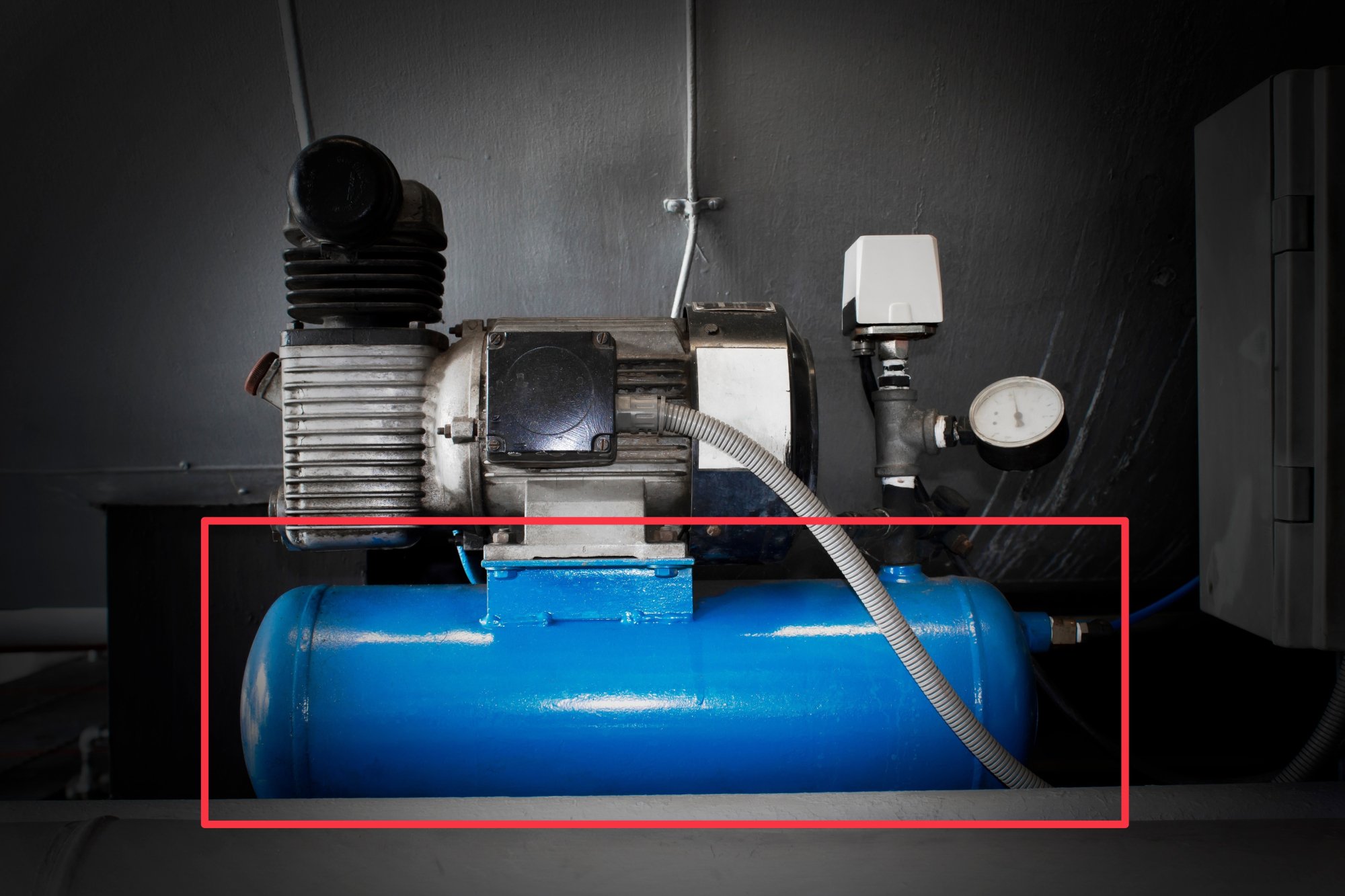
The Air Tank in the CTE Workcell Kit provides compressed air to the other components in the pneumatics system as needed, allowing air to flow smoothly and continuously.
The Air Tank can hold up to 70mL of compressed air, at a pressure of 30 PSI (pounds per square inch).
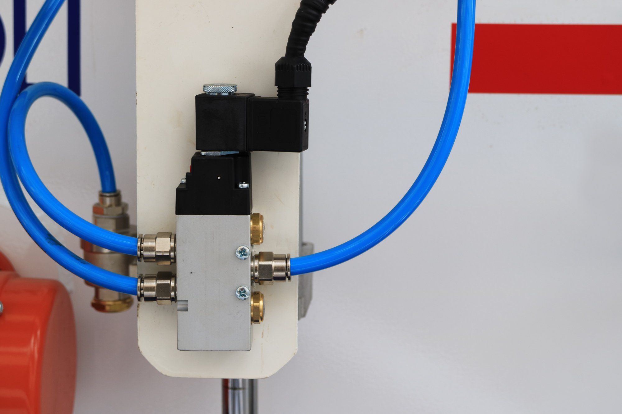
Solenoid
A solenoid controls the flow of air in a pneumatic system. Solenoids receive instructions from the programmable logic controller.
Solenoids function as a switch or valve, directing airflow. This allows the air to be routed to different parts of a pneumatic system to perform different actions.
A solenoid can direct air to one actuator at a time, or to multiple actuators, depending on the complexity of the solenoid.
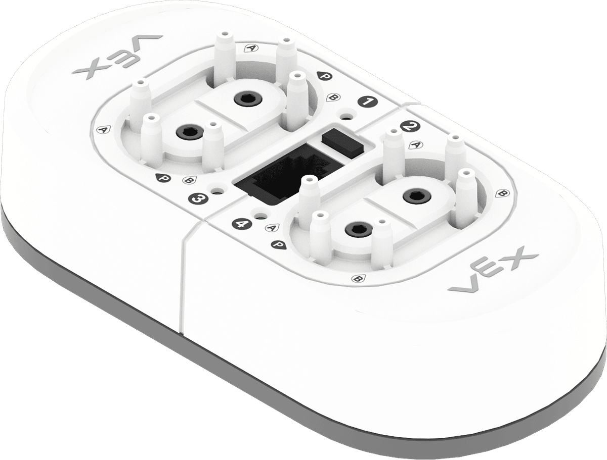
The CTE Pneumatic Solenoid receives instructions from your Robot Brain and directing compressed air to the cylinders.
It can control up to four pneumatic actuators at the same time, directing air to make cylinders extend (push) or retract (pull). The solenoid is key in managing how your pneumatic system works.
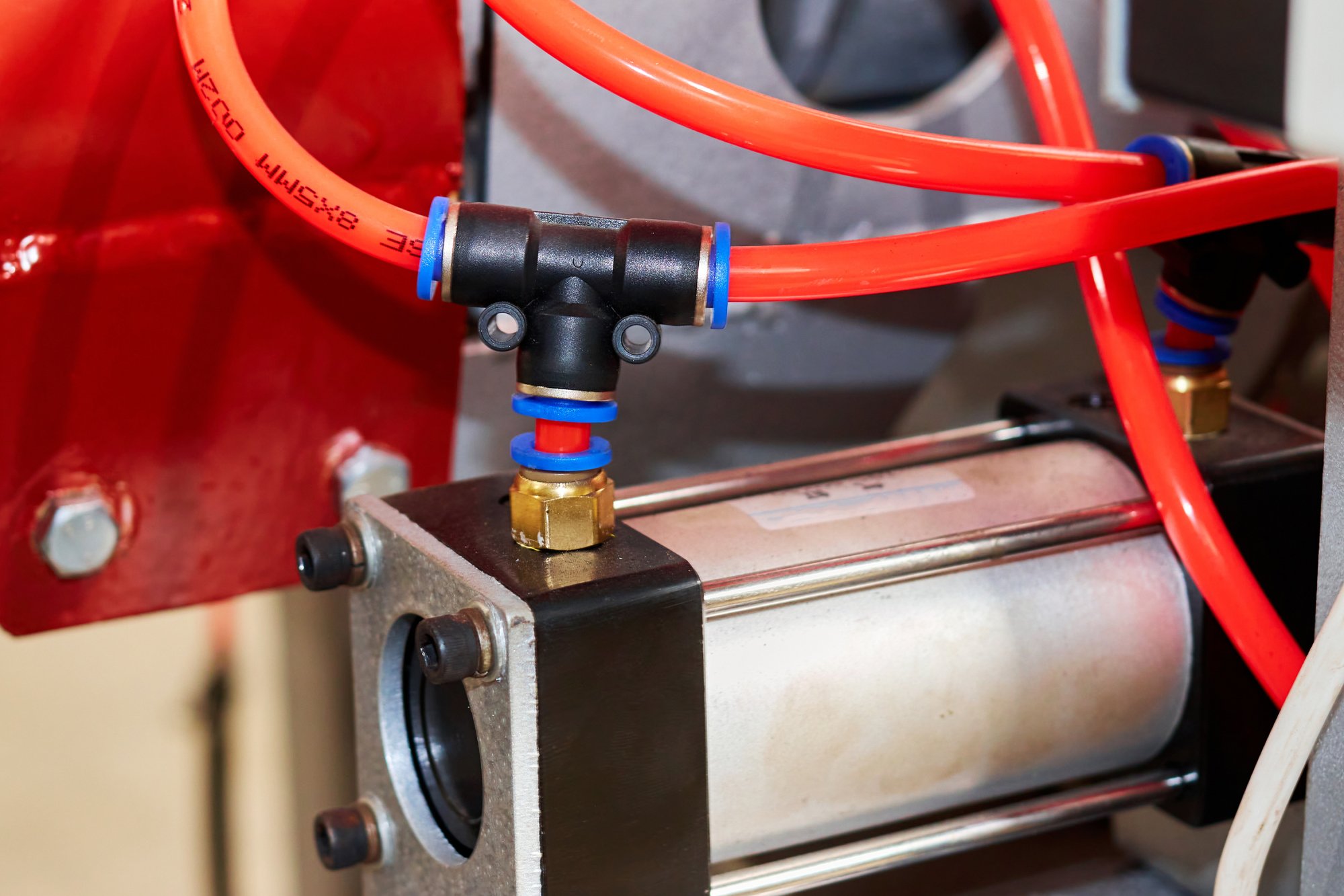
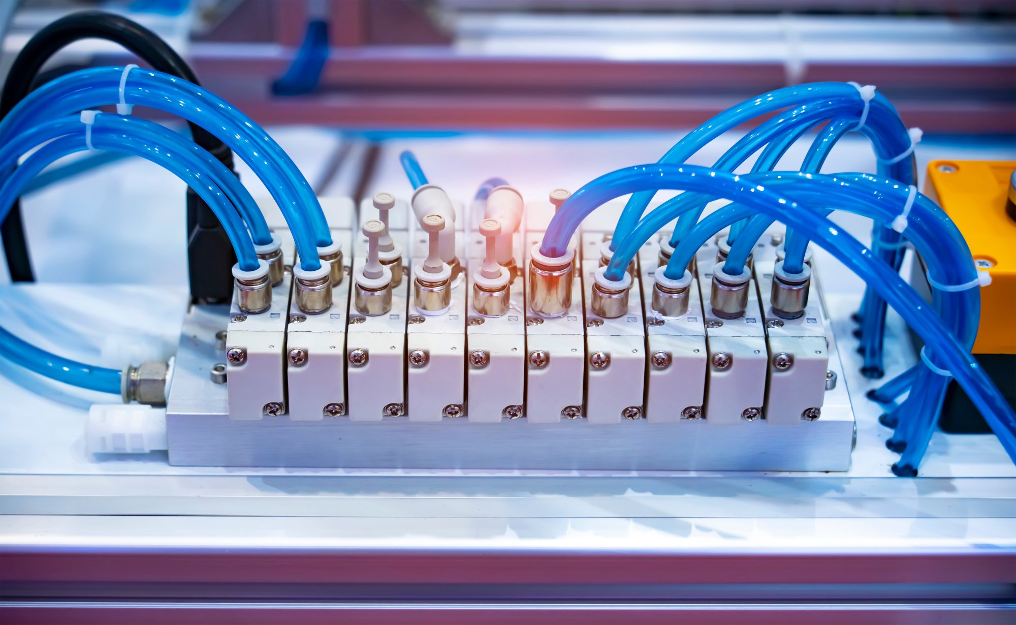
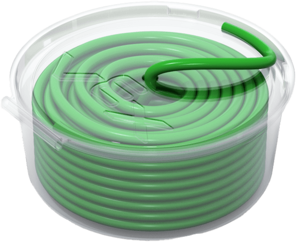
Tubing
Tubing moves compressed air to the various components of a pneumatic system.
Because pneumatic tubing is made from flexible material, such as rubber, nylon or polyurethane, it provides flexibility to pneumatic systems, allowing them to be customized and rearranged as needed.
The Tubing in the CTE Workcell Kit is 4mm in diameter, and can be cut to size as needed.
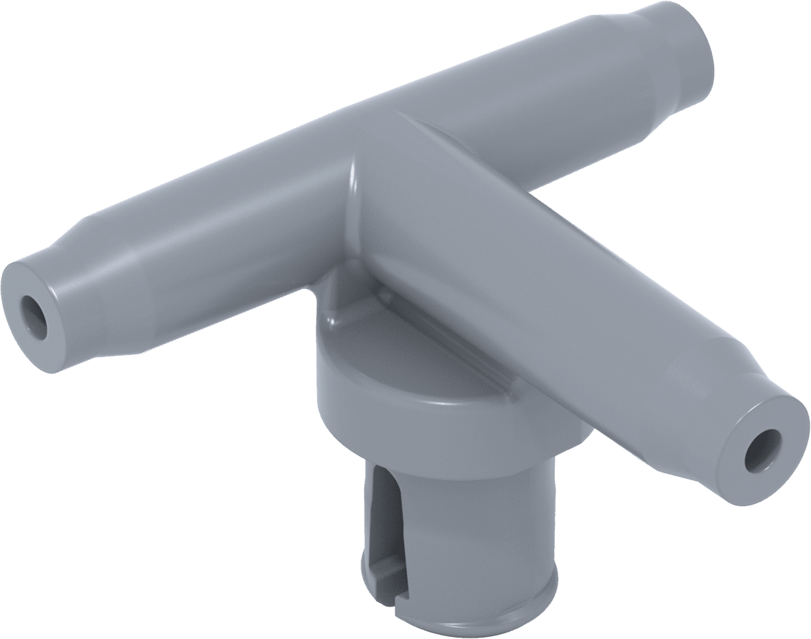
Tee Fittings are used in conjunction with Tubing to control airflow. They can direct air to two different locations in a pneumatic system at the same time.
Actuators
An actuator transforms the potential energy stored in compressed air into kinetic energy. This kinetic energy is then used to perform work through linear motion.
One of the most common types of actuators is a pneumatic cylinder, which is used in applications requiring pushing, pulling, lifting, or pressing actions.

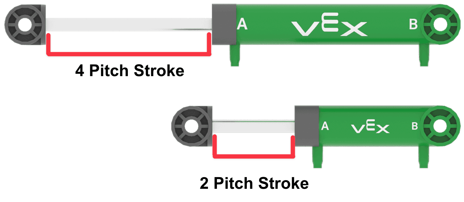
The actuators in the CTE Workcell Kit are Pneumatic Cylinders. They use air pressure to extend or retract, creating a push or pull motion.

There are two different sizes of Pneumatic Cylinders in the CTE Workcell Kit – the 2 Pitch Stroke Pneumatic Cylinder and the 4 Pitch Stroke Pneumatic Cylinder.
The stroke length refers to the measure of the fully extended cylinder.
Activity
Now that you have read about the components of a pneumatic system, it is time to see if you can identify them in a real world setting. In this activity, you will watch a video of a pneumatic system in action, and describe what you see.
In the video, a substance is getting put into plastic containers, then sealed, and covered with a lid on an assembly line. There are four main mechanisms shown, that all have a series of tubes connecting them. The first features a nozzle that fills a plastic container, then places it on a moving disk which circulates clockwise to the next stage of assembly. The second is a suction cup arm that flips up and down to retrieve a metal sheet and seal the container. Third, a similar device flips up and down to place the lid on top of the sealed container. Finally, a metal arm extends and retracts to push the completed container to the next part of the assembly line.
Activity
- Watch the video above and observe the actions of the workcell.
- In your engineering notebook, record each pneumatic component you can identify. Describe how it is functioning to make a product. Be sure to indicate when and where you see linear movement and rotational movement. You can use words, images or both.
- You may need to watch the video multiple times to record each component.
Check Your Understanding
Before moving on to the next Lesson, ensure that you understand the concepts in this Lesson by answering the following questions in your engineering notebook.
Check Your Understanding questions > ( Google Doc / .docx / .pdf )
Select Next > to move on to the Mid Unit Reflection.