
Background
In this Fun Frogs Unit, students will explore the frog life cycle. They will use VEX GO Kits and classroom materials to create a habitat for their frog then create four of the stages of the frog life cycle. Students will investigate frog habitats and how these frog life cycles allow the frog to adapt to its environment.
What is a Habitat?
A habitat is an area that is lived in by a particular organism. Organisms are individual living things. Animals, plants, or other parts of the living environment are all organisms. Organisms usually have five basic needs: air, water, food, energy, and a place to live. However, not all living things need all these at the same time.
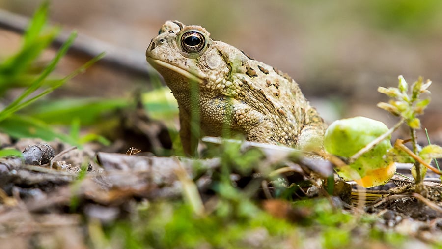
Most animals live in one type of environment because they are best suited to it or are adapted to the environment. For example, animals such as frogs, toads, and ducks have webbed feet to help them swim in the water. There are many different types of habitats and many different kinds of adaptations to fit into each. When people speak about adaptation, they often mean a 'feature' (a trait) which helps an animal survive.
What is the Frog Life Cycle?
A life cycle is the stages an organism goes through during its life. Throughout the Fun Frogs Unit, students will build four of the different stages a frog goes through. The stages of the frog life cycle are:
- Eggs
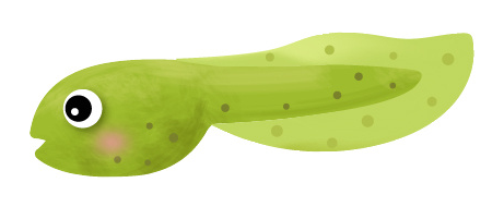
- Tadpole
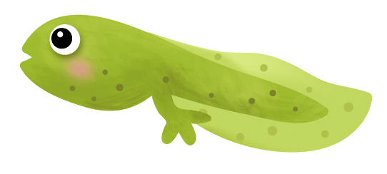
- Tadpole with two legs
- Froglet (also known as tadpole with four legs)
- Adult frog
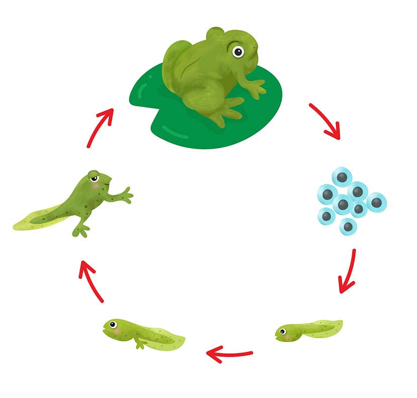
Frogs begin their life cycle when an adult female frog lays eggs in a body of water. Once they emerge from the egg, the frog moves into its first stage of life. A tadpole is a young frog that breathes and lives in the water. They hatch from small eggs laid in a pond or lake.
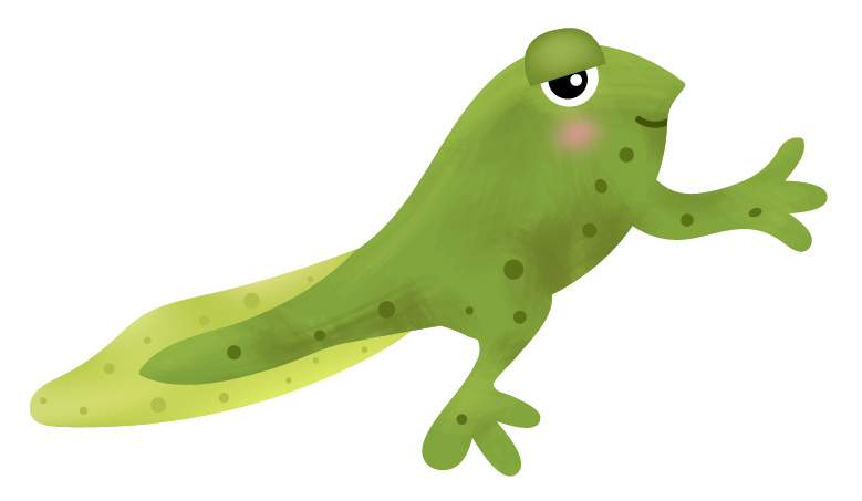
As a tadpole matures, it grows the two back legs. This stage in the life cycle is also known as tadpole with two legs.
The tadpole with two legs then grows the two front legs. This is when the frog begins to grow lungs and the gills disappear. The froglet, or tadpole with four legs, also begins to lose its tail during this stage.
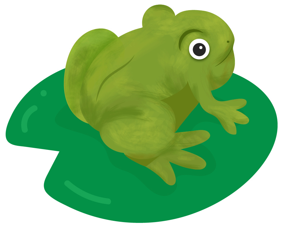
After the tail is shed and the frog has fully grown lungs, it is considered an adult frog. A frog can now leave the water and live on land. Female frogs will return to the water to lay eggs and begin the cycle again.
VEX GO Pieces
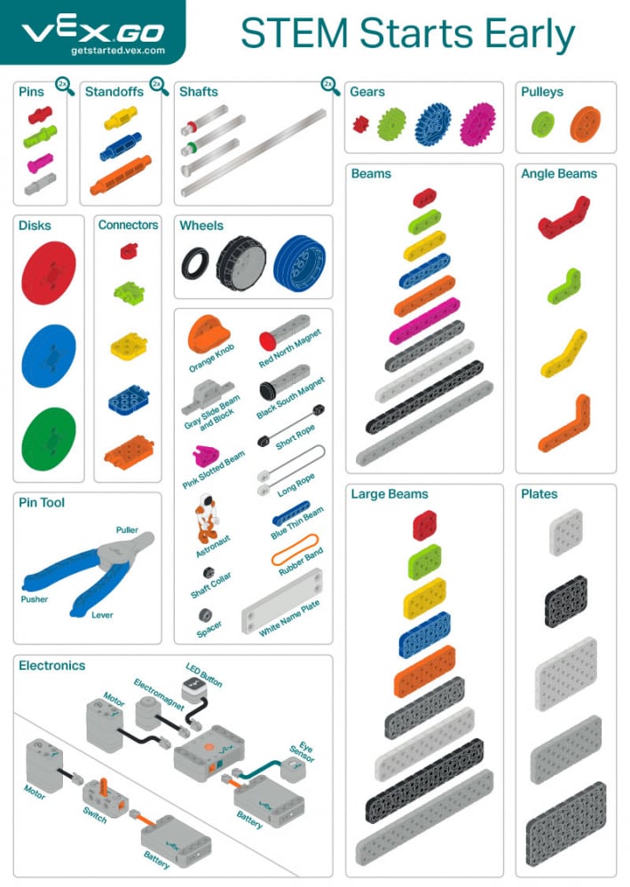
The following VEX GO pieces are essential parts of the Frog Life Cycle build. The VEX GO Poster illustrates all VEX GO pieces and organizes them according to their function in a build.
The VEX GO Kit poster lists the major categories of parts: pins, standoffs, shafts, gears, pulleys, disks, connectors, wheels, beams, angle beams, large beams, plates, and electronics. The poster also calls out the Pin Tool and the other pieces included in the kit.
Pins and Standoffs
Because pins and standoffs connect other pieces together, students may confuse their uses. Standoffs connect two pieces but leave a space in between. Each kind of standoff has a different width gap that will be created by its use.
Pins connect two or more pieces so that they lay flush with one another. The Red Pin can connect with one piece on each side. In contrast, the Green Pin can connect one piece on one side and with two pieces on the other side.
Connectors
Pins and standoffs create connections between pieces that are in parallel to each other. However, connectors create connections at a 90 degree, right angle. The Green Connector and Orange Connector allow right angle connections as well as parallel connections.
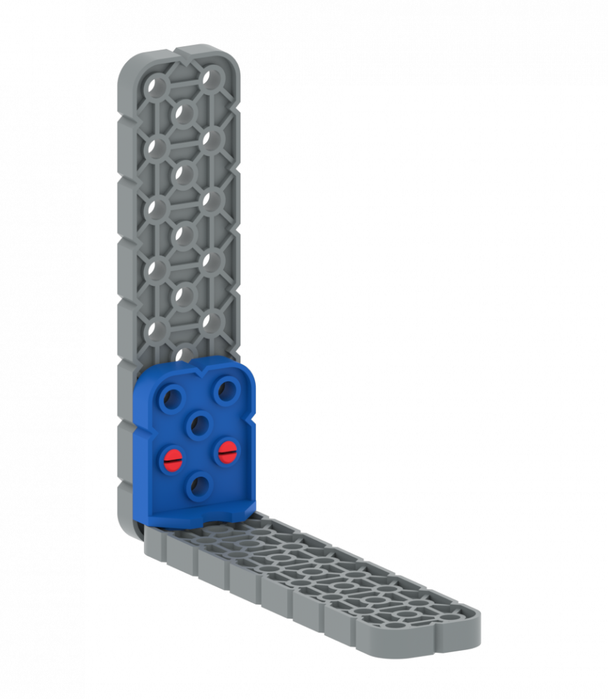
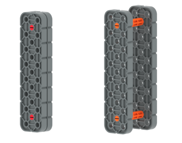
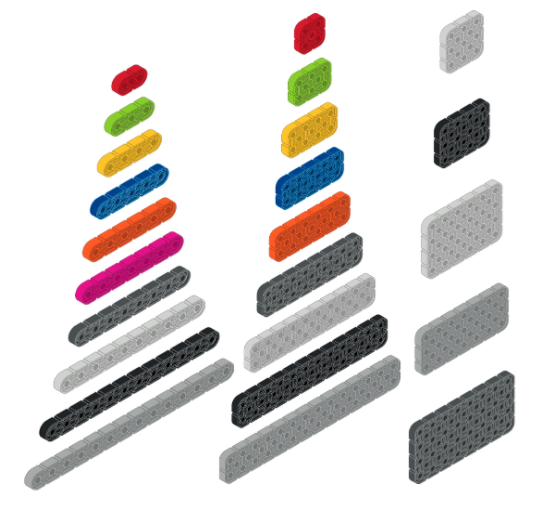
Beams and Plates
Beams and plates are used to create the structural base of most builds. These are flat pieces with varying widths and lengths. The width and length of a beam or plate can be measured by the number of holes on the piece. Students will learn as they begin to build that beams (one hole in width) are not as stable as large beams (2 hole width) or plates (3 or more hole widths).
There are several unique beams including four Angle Beams. These beams create angles at 45 or 90 degrees. Other unique beams include the Blue Thin Beam which has one hole that will fit a shaft and allows the beam to rotate, and has additional holes for standard connections. The Pink Slotted Beam can be used to secure the Rubber Band or ropes in a build.
Pin Tool
While students become familiar with the VEX GO Kit, they will inevitably need help separating pieces. The Pin Tool helps students to separate pieces through three different functions: the Puller, the Lever, and the Pusher. The Puller is best suited for removing pins that have one end free. To use the Puller, insert the pin into the slot at the nose, squeeze the Pin Tool, and pull back. The pin should be easily removed from the hole.
In the case that a pin is not partially exposed, the Pusher can be used to push part of the pin free. The Lever is most appropriate when attempting to disconnect two beams or plates that are flush with one another. The Lever can be inserted between the two pieces and used to separate the connected pieces. Watch the animation below to see how to use the Pin Tool.