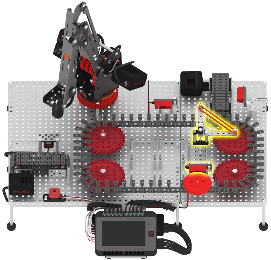
Divert the Red Disk
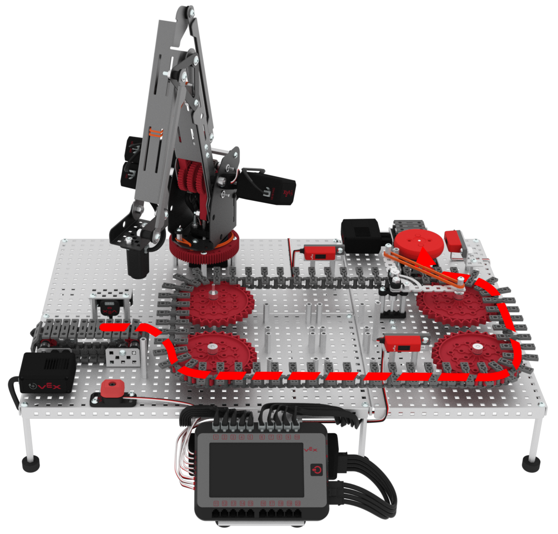
The red disk, acting as a faulty package or product, will move through the following path:
The red disk will begin at the entry conveyor in front of the Optical Sensor.
The red disk will then be loaded onto the transport conveyor from the entry conveyor.
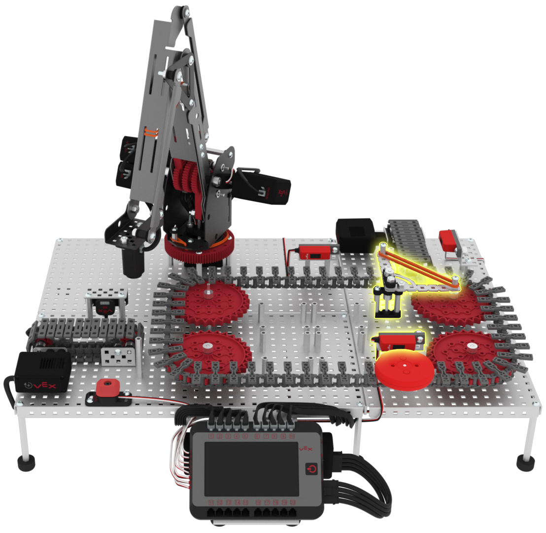
Once the red disk is loaded onto the transport conveyor, it will pass in front of the load sensor. When the red disk passes in front of the load sensor, the diverter needs to be set to position in order to divert the red disk to the exit conveyor.
Once the red disk is on the exit conveyor, it will pass in front of the exit sensor. When the red disk passes in front of the exit sensor, all conveyors will need to stop.
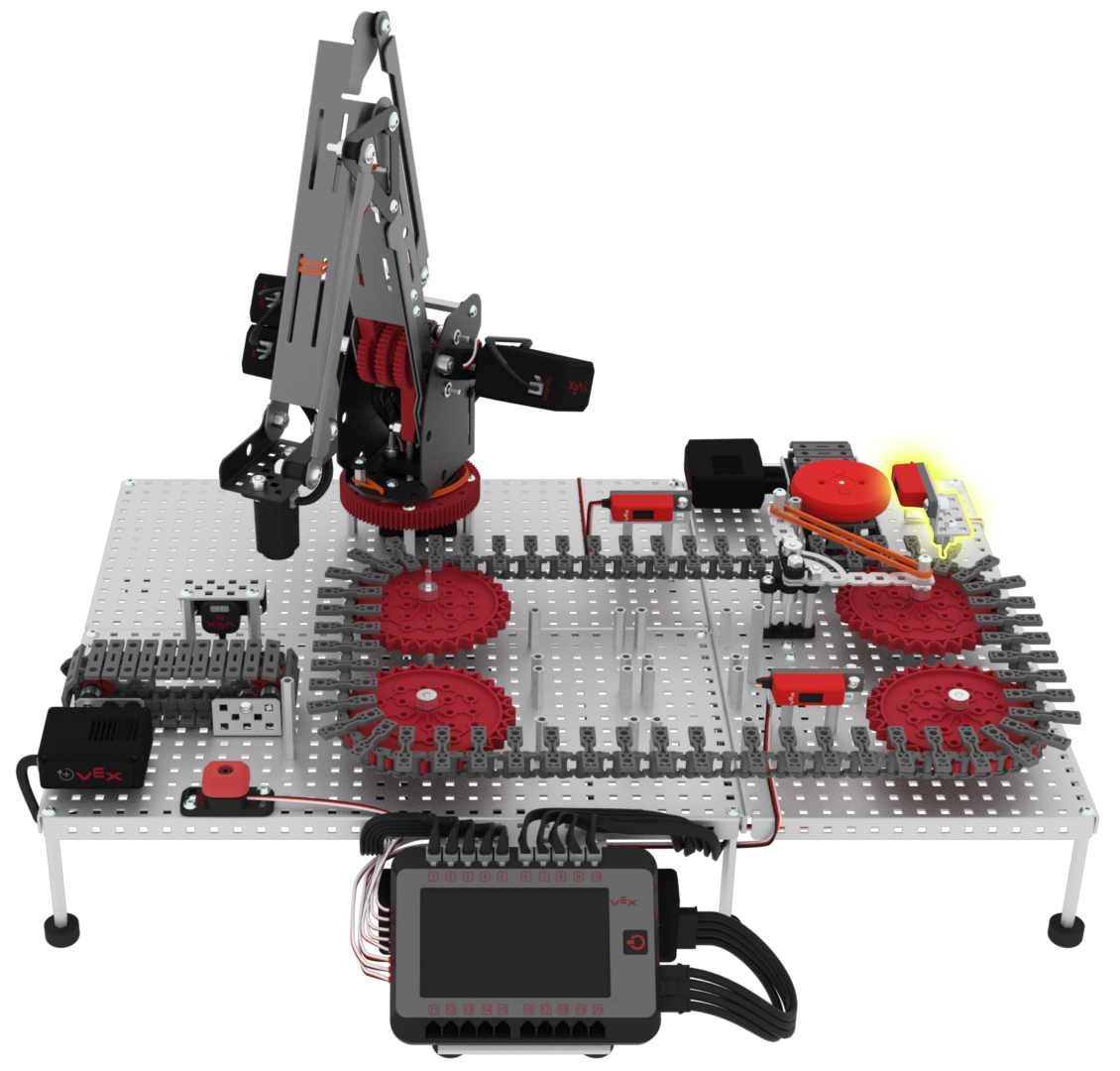
The red disk will have followed this complete path to be diverted off of the exit conveyor.

Now that you have recorded the low and high threshold values of the Line Trackers and understand the path that the red disk will travel, you will now code the sensors using the Line Tracker values to divert a red disk off of the Workcell.
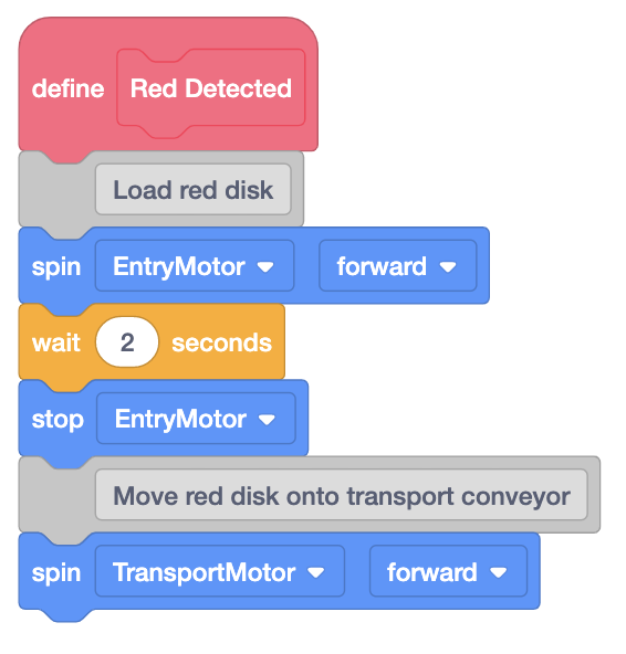
Add blocks to the {Define My Block} block for the red disk to create the stack of blocks shown in this image.
These blocks will code the entry and transport conveyors to spin forward, so that the red disk moves from the entry conveyor onto the transport conveyor.
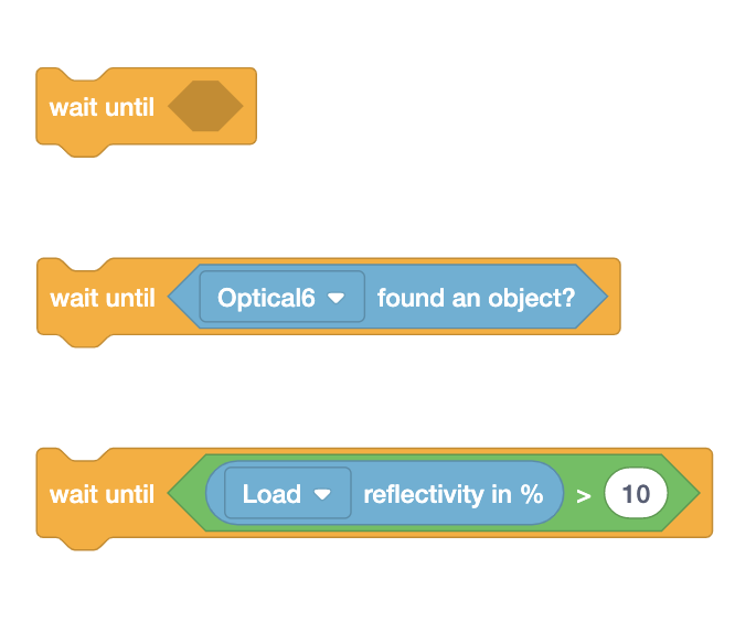
For Your Information
The [Wait until] block waits for a Boolean block to report true before moving to the next block in the stack.
In this project, the [Wait until] block will be used to wait until the Optical Sensor detects a disk, and also wait until a disk is detected by the Line Tracker that is reported by the (Reflectivity of) block.
The (Reflectivity of) block reports the amount of light reflected using the Line Tracker.
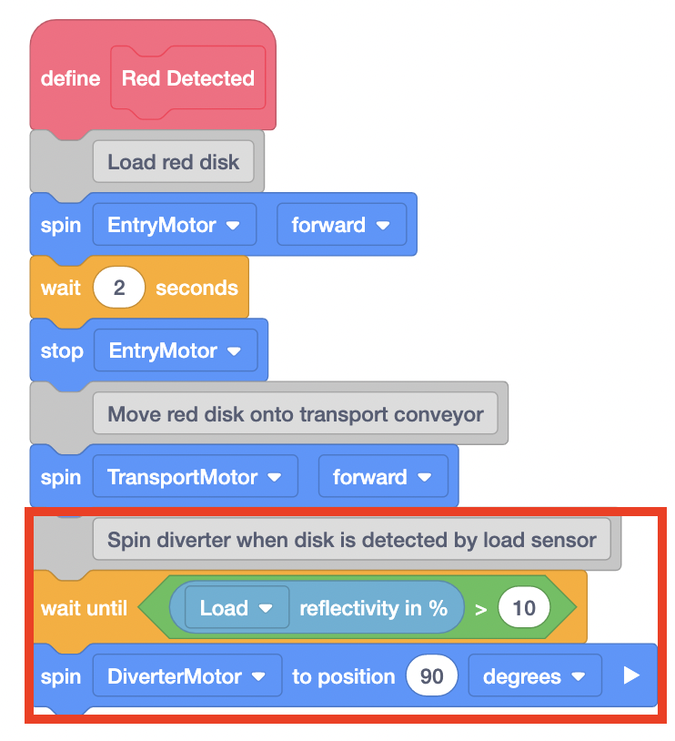
Add blocks to the project to create the stack of blocks shown in this image.
Use your low threshold value for the load sensor in the <Greater than> block and not the one shown in this image.
These blocks will code the transport conveyor to spin forward until the load sensor detects a light value greater than the lower threshold value.
Then, once the red disk is in front of the load sensor, the diverter will be set to the 90 degree position to divert the red disk to the exit conveyor.
Load a red disk onto the entry conveyor and download and run the project.
The red disk will travel from the entry conveyor, onto the transport conveyor, and then be diverted off onto the exit conveyor.
Once the red disk has been moved onto the exit conveyor, stop the project.
If the red disk has not been diverted off onto the exit conveyor, notify your teacher.
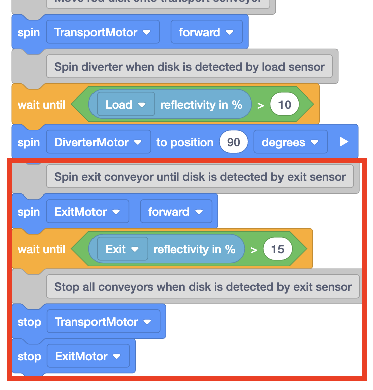
Add blocks to the project to create the stack of blocks shown in this image.
Use your low threshold value for the exit sensor in the <Greater than> block and not the one shown in this image.
These blocks will code the exit conveyor to spin forward until the exit sensor detects a light value greater than the lower threshold value.
Then, once the red disk is in front of the exit sensor, all conveyors will stop spinning.
Load a red disk onto the entry conveyor and download and run the project.
The disk will follow the shown path to be diverted off of the exit conveyor.
Once the red disk is in front of the exit sensor and all conveyors stop spinning, stop the project and check in with your teacher.
If the red disk did not follow the path shown, notify your teacher during the check in.