
The Complete Look of the Build
![]() Teacher Toolbox
-
Facilitating the Seek Section
Teacher Toolbox
-
Facilitating the Seek Section
In this Seek section, groups will go through the process of preparing for the Play section as they turn on their Brain, review their port configurations, and record their mastering values.
What the Teacher Will Do:
- Provide each group with a printed Seek Checklist (Google / .docx / .pdf).
- Instruct groups to follow each item in the checklist and check in when the list is completed.
- For groups that finish early and have checked in, encourage them to help other groups complete their checklists.
Go to the V5 Workcell Educator Certification for additional suggestions on facilitating the Seek section.
![]() Teacher Tips
Teacher Tips
- If any groups need information about the battery, including how to charge or how to connect the battery to the Brain, see this section of the Knowledge Base.
- For additional help connecting the Brain to a device, see this Knowledge Base article.
- If any groups do not have access to VEXcode V5 on their device, see this page for how to access VEXcode V5.
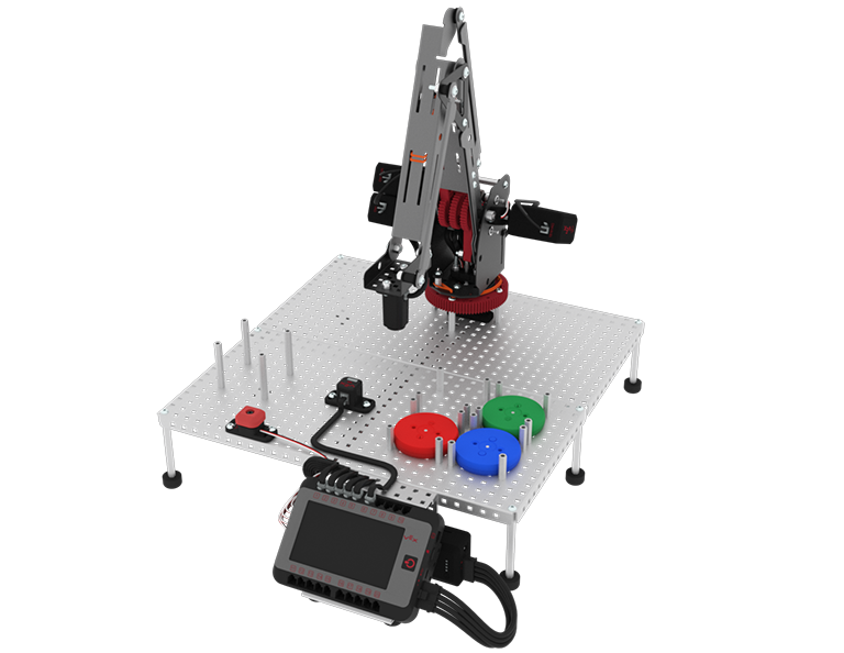
In this Seek section, you will be preparing for the Play section by turning on your Brain, reviewing port configurations, and recording mastering values. You will follow the Seek Checklist to ensure everything is ready for Play. Your Workcell build should match the image below.
Seek Checklist
Prepare for the rest of the Lab by ensuring each of these items have been complete.
- Is the battery charged?
- Is the battery attached to the Brain?
- Is the Brain on and connected to your device?
- Is VEXcode V5 open?
- Are the port configurations correct? Reference the Port Configurations section on this page to check if they are correct.
- Check and record mastering values. Follow the steps on the Mastering Values page in the Seek section for how to find those values.
Port Configurations
In order for the arm mounted on the Workcell to work as intended, each joint has a potentiometer and motor that will need to be plugged into its assigned port. The breakdown of where to insert each of these cables is covered in the Lab 1 Build Instructions.

If you are using the Standard Config, each joint has a specific port assigned to it(as seen in the table below). If you are using a Custom Config, each joint can be assigned to your desired port. The Potentiometers will go into the lettered, 3-Wire Ports and the Motors will go into the numbered, smart ports.
| Joint Number | Motor - Smart Port | Potentiometer - 3-Wire Port |
|---|---|---|
| 1 | 1 | A |
| 2 | 2 | B |
| 3 | 3 | C |
| 4 | 4 | D |
Measuring and Making Your Own Cables
As you build your Workcell, you may want to make your own customized V5 Smart Cables instead of using the pre-determined sized cables. To do so, follow the instructions in the Crimping Tool Knowledge Base Article. For help with measuring these cuts, as well as measuring many different pieces in the VEX V5 ecosystem, view this article for information on how to Use the Printable VEX V5 Parts Ruler.
Installing V5 Workcell Rubber Bands
Installing the rubber bands on the Workcell is crucial for reliable and repeatable movements of the arm. Think of these rubber bands as the muscle of the Workcell. Installing these rubber bands correctly ensures that your Workcell will function as intended. If you notice that your V5 Workcell’s arm is not moving accurately, shaking, or generally not moving in a smooth manner, the rubber bands may not be installed correctly, or at all. View this article from the VEX Library for helpful tips and tricks, as well as animations for how to install your rubber bands.
Additional Devices:
- Bumper Switch: 3-Wire Port E
- Electromagnet: Smart Port 5
- Optical Sensor: Smart Port 6