This page's translation was completed by machine translation. Please forgive any possible errors.
Program Linear Movement
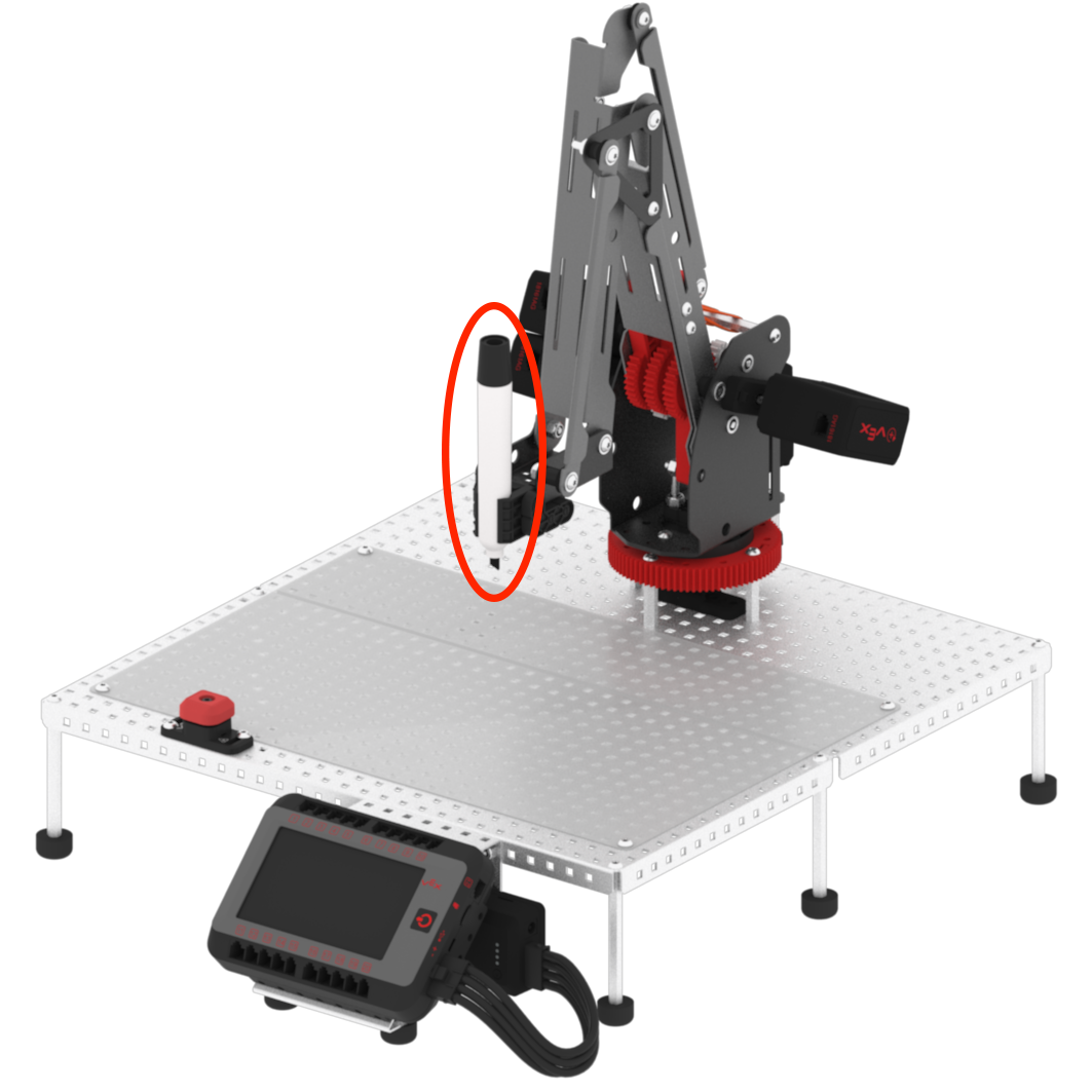
Change the color of the dry-erase marker on the arm mounted on the V5 Workcell. This will be used to see the difference between linear and joint movements.
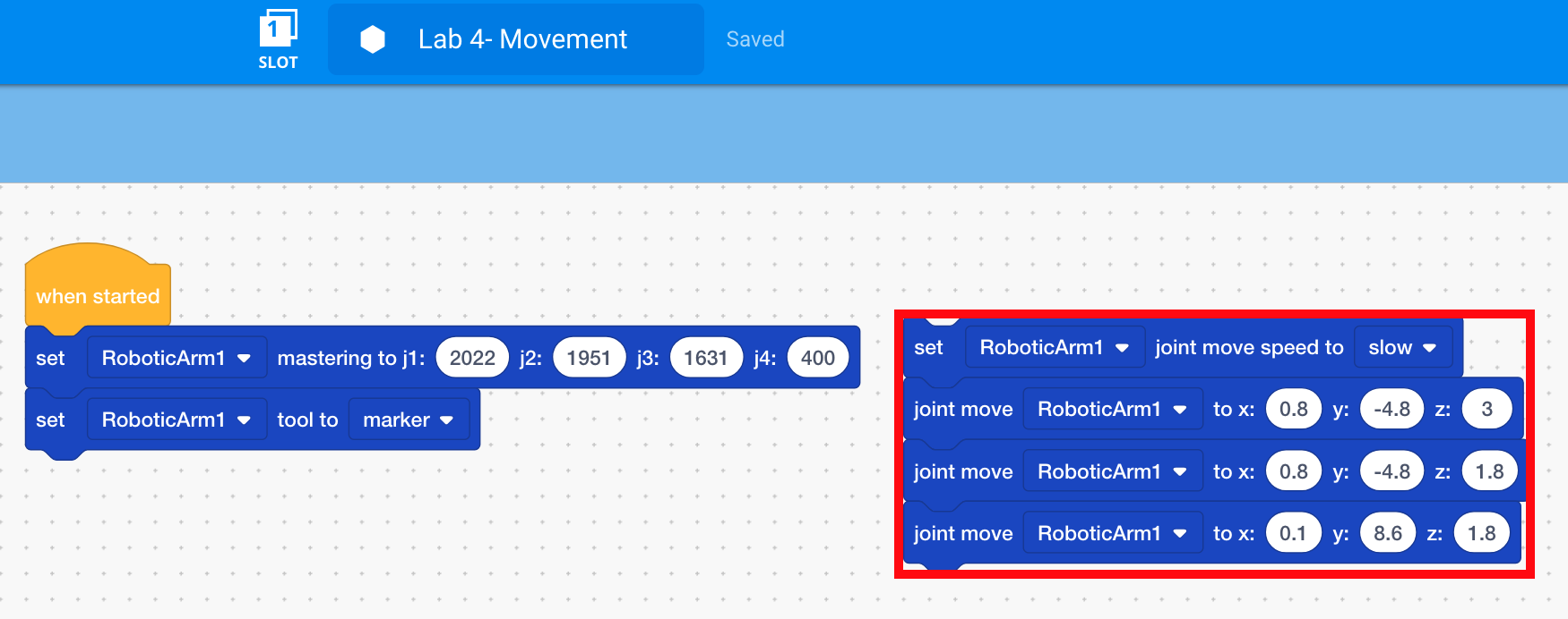
Detach the [Joint move speed] and three [Joint move] blocks from the [Set tool] block, but do not delete them. Place them somewhere else in the Workspace. Blocks that are not attached to hat blocks, like the {When started} block, are not executed when the project is run.
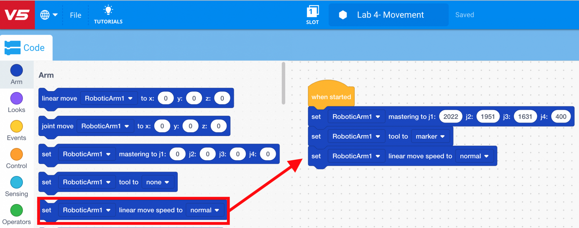
To ensure the arm mounted on the V5 Workcell does not move too quickly, select and drag the [Set linear speed] block from the ‘Arm’ category in the Tool Box and attach it to the [Set tool] block.
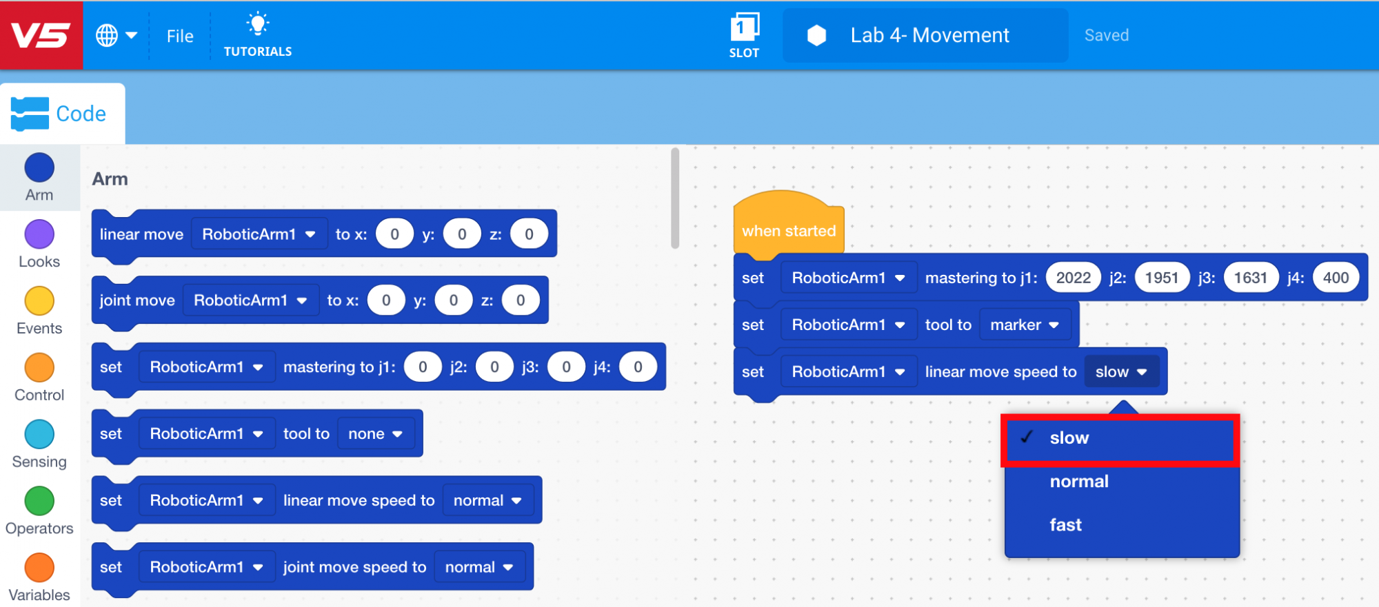
Set the speed to ‘slow.’
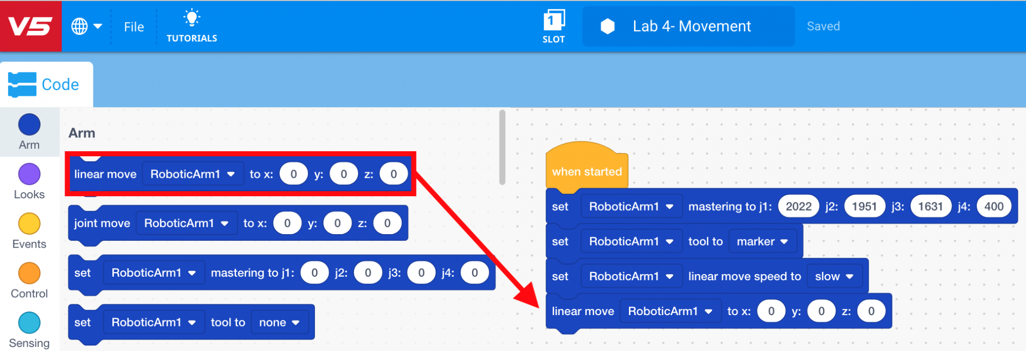
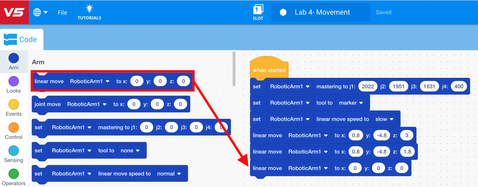
Select and drag the [Linear move] block from the ‘Arm’ category in the Tool Box and attach it to the [Set linear speed] block.
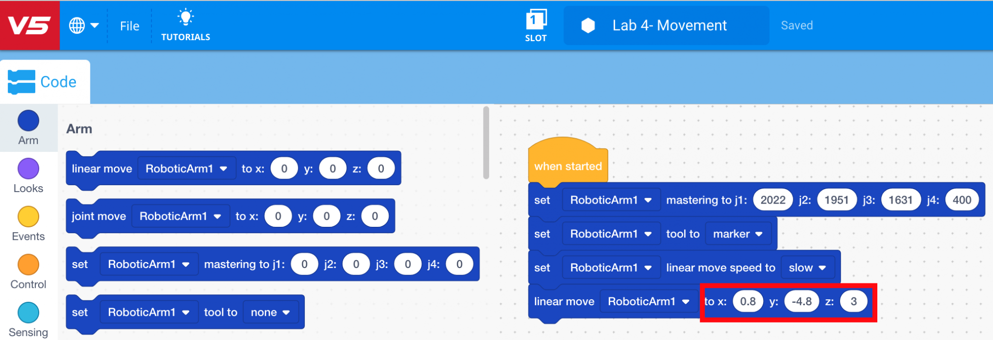
Input the (x, y, z) coordinates of the location above Point 1 into the [Linear move] block.
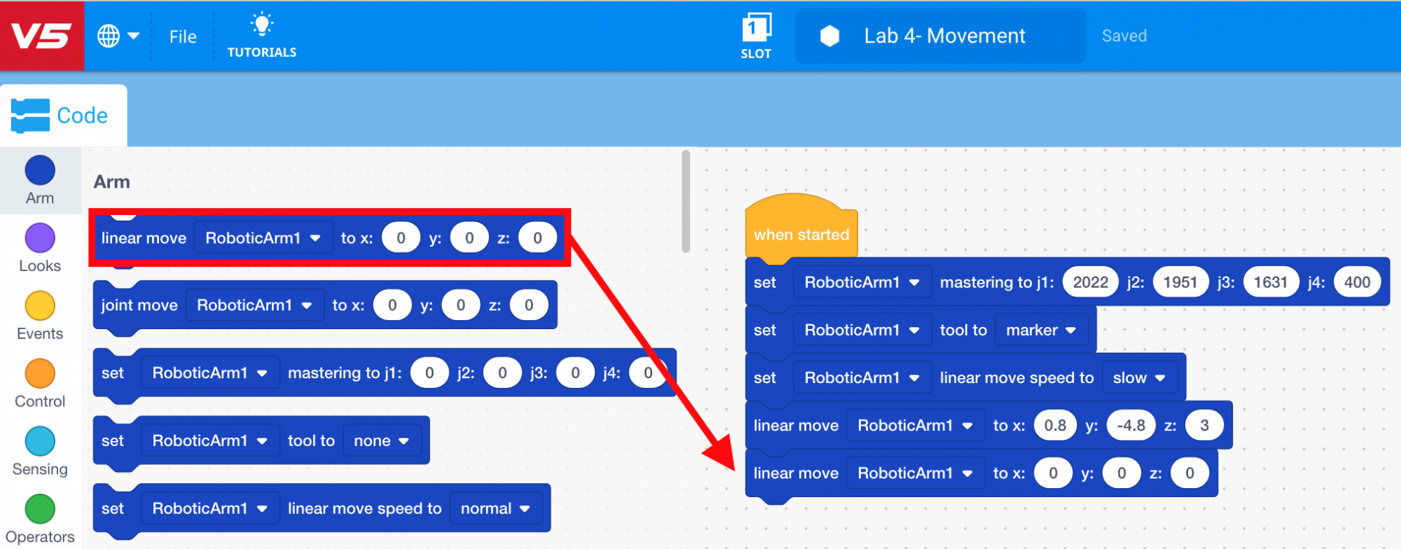
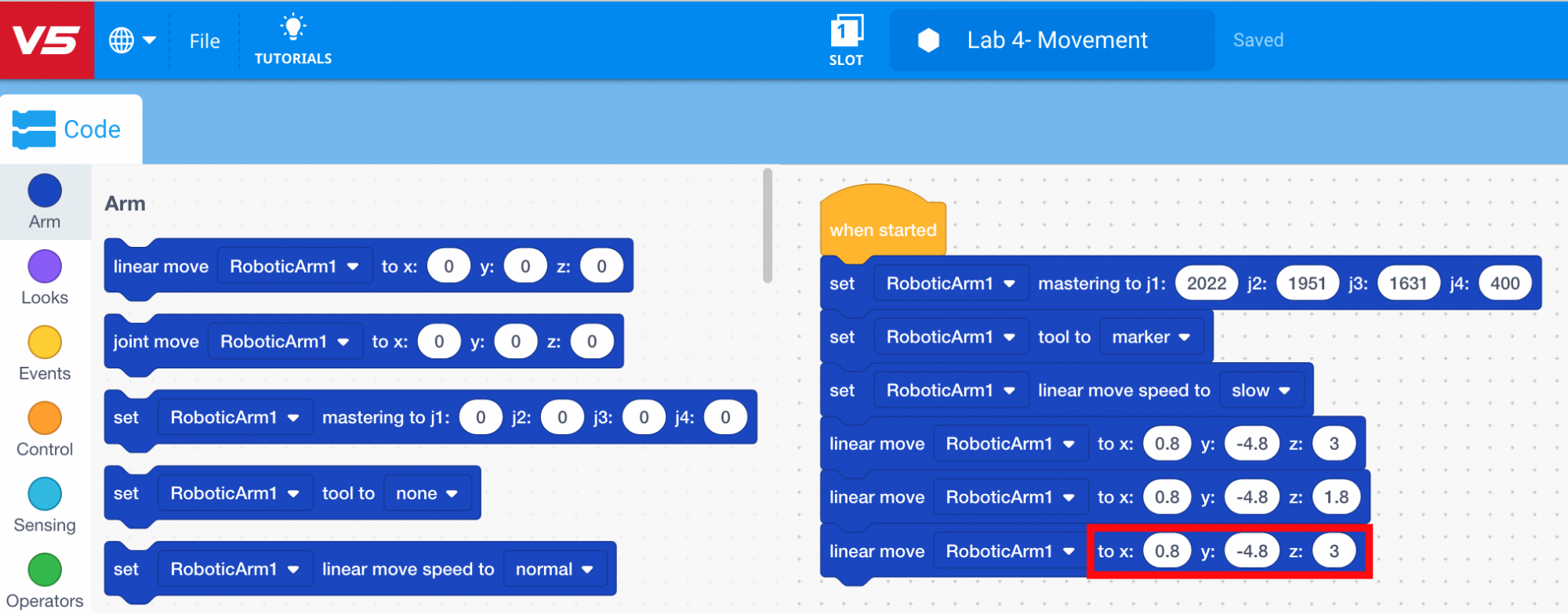
Select and drag another [Linear move] block from the ‘Arm’ category in the Tool Box and attach it to the first [Linear move] block.
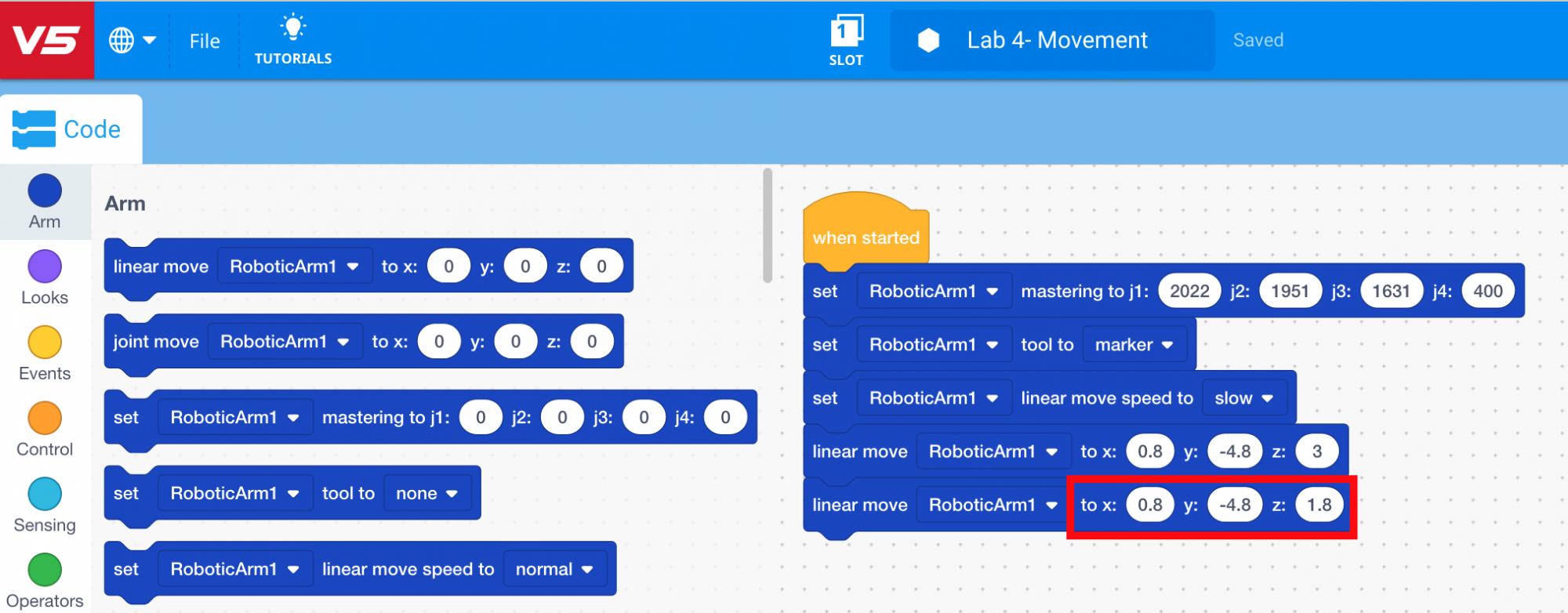
Input the (x, y, z) coordinates of Point 1 into the second [Linear move] block.
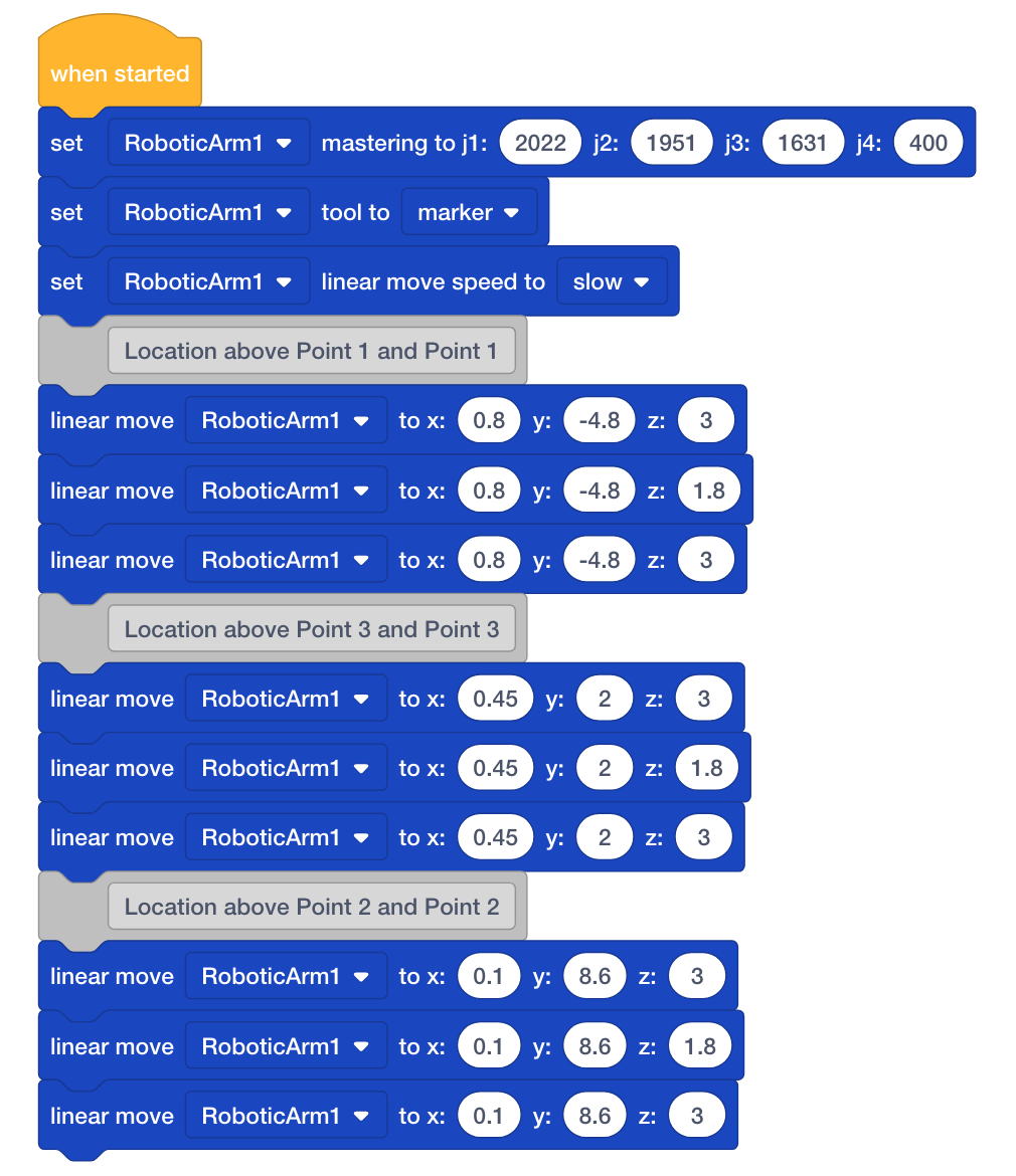
Select and drag another [Linear move] block from the ‘Arm’ category in the Tool Box and attach it to the second [Linear move] block.
Input the (x, y, z) coordinates of the location above Point 1 into the third [Linear move] block. This ensures the arm mounted on the V5 Workcell will raise up before moving to the location above Point 3. Note: the first and third [Linear move] blocks should be exactly the same.
Repeat steps 32-37 two more times to add six additional [Linear move] blocks and input the (x, y, z) coordinates of the Points 2 and 3, as well as the locations above Points 2 and 3. Ensure the coordinates for Point 3 and the location above Point 3 are added first, to ensure the arm mounted on the V5 Workcell will move in the correct order of points:
a. Above Point 1
b. Point 1
c. Above Point 1
d. Above Point 3
e. Point 3
f. Above Point 3
g. Above Point 2
h. Point 2
i. Above Point 2
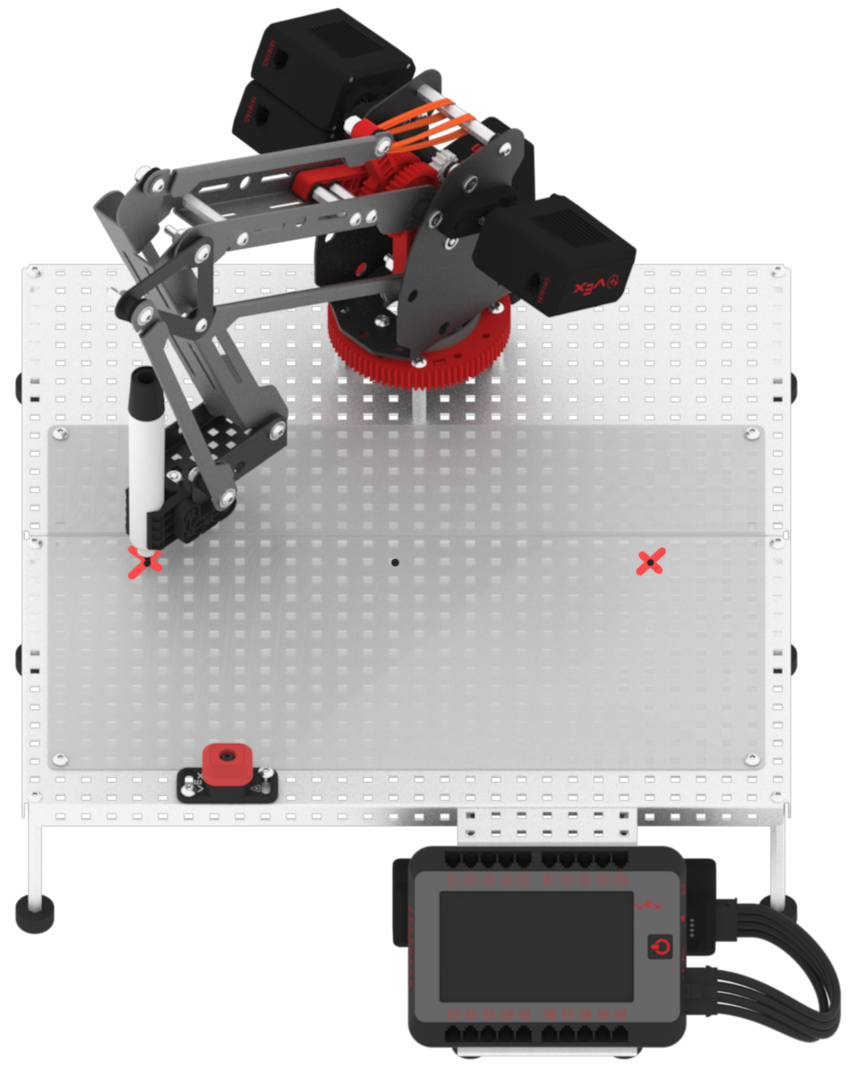
Download and run the project. Note: if the dry-erase marker is not drawing well, adjust the z-axis values to provide more force.
Observe that the arm mounted on the V5 Workcell drew three dots at Points 1, 2, and 3 using the dry-erase marker.
You are about to navigate to Google Docs. The linked document is in English. For instructions on translating the document to another language, please refer to
Google Docs’ translation guide
.
Note: To use the translation feature, first make a copy of the document.
This option will prevent this dialog from appearing again in the future.