Exploring Velocity - Blocks-based
![]() Teacher Toolbox
Teacher Toolbox
-
Activity Outline
This exploration will first introduce students to setting the velocity for driving and then ask them to explore how the velocity of the robot affects its momentum. Click here (Google / .docx / .pdf) for the outline of this activity. Understanding the momentum of the robot will be an important concept to apply to the Strike Challenge bowling game. -
What the Students will Program
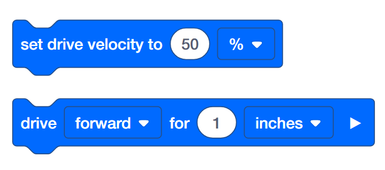
Using the Speedbot (Drivetrain 2-motors, No Gyro) template project allows the students to change the velocity settings of the [Drive for] block simply by adding a [Set drive velocity] block to a stack. The guided part of the activity has students work with the [Set drive velocity] block and the end of the activity asks them to apply their skills for programming velocity to tests of momentum and energy transfer.
Speedbot is ready to drive at different velocities!
This investigation will help you to learn more about programming the Speedbot to drive at speeds that are best suited for the task. In the Strike Challenge at the end, you will need to find a velocity for the Speedbot that allows it to be fast and have great momentum but remain in control in order to hit the ball at a good angle and with great force.
VEXcode V5 that will be used in the first part of this investigation:
![]() Teacher Tips
Teacher Tips
If this is the student’s first time using VEXcode V5, they can reference the Tutorials at any time during this exploration. The Tutorials are located in the toolbar.

To find out more information about the block, open the Help and then select the block you want to read about.
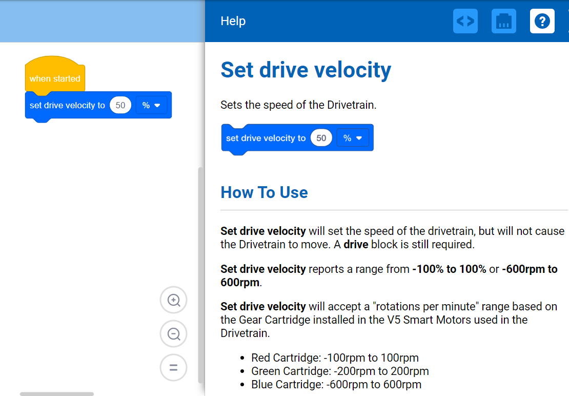
Each group of students should get the hardware required and the group’s engineering notebook. Then open VEXcode V5.
| Quantity | Materials Needed |
|---|---|
| 1 |
Speedbot Robot |
| 1 |
Charged Robot Battery |
| 1 |
VEXcode V5 |
| 1 |
USB Cable (if using a computer) |
| 1 |
Engineering Notebook |
| 1 |
Ball (the size and shape of a soccer ball) |
| 1 |
3m x 3m clear space |
| 1 |
Meter stick or Ruler |
| 1 |
Roll of tape |
| 1 |
Data table |
![]() Teacher Tips
Teacher Tips
-
Model each of the steps for checking that the Speedbot is ready so that students will get into the habit of doing so.
Step 1: Preparing for the Exploration
Preparing for the Exploration
Before you begin the activity, do you have each of these items ready?
-
Are all the motors plugged into the correct ports?
-
Are the smart cables fully inserted into all of the motors?
-
Is the Brain turned on?
-
Is the battery charged?
Step 2: Start a New Project
Before you begin your project, select the Speedbot (Drivetrain 2-motors, No Gyro) - Template project. The template project contains the Speedbot's motor configuration. If the template is not used, your robot will not run the project correctly.
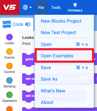
- Open the File menu.
- Select Open Examples.
![]()
- Select and open the Speedbot (Drivetrain 2-motors, No Gyro) template project.
- Rename your project Drive Velocity because we will be using the [Set drive velocity] block.
- Save your project.
-
For help with saving a project, review the Tutorials inside VEXcode V5.

-
-
Check to make sure the project name Drive Velocity is now in the window in the center of the toolbar.

![]() Teacher Tips
Teacher Tips
-
Make sure that the students have selected the Speedbot (Drivetrain 2-motors, No Gyro) template project.
-
You can point out to the students that there are several templates to select from on the Examples page. As they build and use other robots, they will have a chance to use different templates.
![]() Teacher Toolbox
Teacher Toolbox

- Saving Projects
Point out that when they first opened VEXcode V5, the window was labeled VEXcode Project and it was not saved (indicated on the toolbar). VEXcode Project is the default project name when VEXcode V5 first opens. Once the project is renamed Drive Velocity and saved, the display updates to Saved. Using this window in the toolbar, it is easy to check that the students are using the correct project and it is saved.
Once a project is initially saved, VEXcode V5 autosaves any subsequent changes, as indicated by the message next to the project name.
Tell the students that they are now ready to begin their first project. Explain to the students that by following a few simple steps, they will be able to create and run a project that will set the velocity of the Speedbot’s drivetrain. - Stop and Discuss
This is a good point to pause and have the students review the steps that were just completed on starting a new project in VEXcode V5 individually or in groups. Ask the students to reflect individually before sharing within their group or to the whole class.
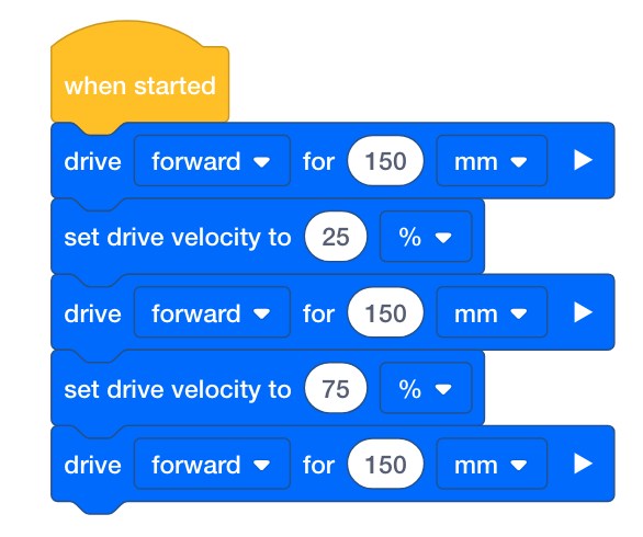
Step 3: Drive Forward for 450 mm at Different Velocities
-
Build this project in VEXcode V5.
![]() Teacher Toolbox
Teacher Toolbox
Notice that in this stack the second and third blocks are the same as the fourth and fifth blocks. After adding the third block, the student can right- or long-click on the second block and choose Duplicate to add the fourth and fifth blocks. Then the velocity of the fourth block can be changed to 75%.

-
Select on the Slot icon. You can download your project to one of the eight available slots in the Robot Brain. Select slot 1.
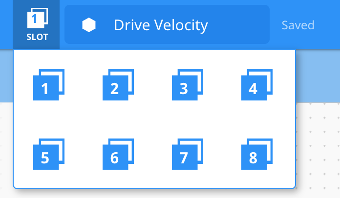
-
Connect the robot to your computer or tablet. The Brain icon in the toolbar turns green once a successful connection has been made.

-
Then, click the Download button on the toolbar to download the Drive Velocity project to the Robot Brain.
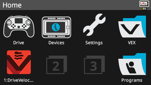
- Check to make sure your project has downloaded to the Speedbot’s Brain by looking at the Robot Brain’s screen. The project name should be listed in Slot 1.
-
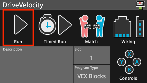
Run the project on the Speedbot robot by selecting the project and then pressing Run.
![]() Teacher Toolbox
Teacher Toolbox
-
Stop and Discuss
Ask the students to predict what they think will happen when this project is downloaded and run on the Speedbot robot. Tell the students to record their predictions in their engineering notebooks. If time allows, ask each group to share their prediction.Students should predict that the Speedbot will first move forward at its default velocity (50%), then slower (25%) than the default velocity, and then faster (75%) than the default velocity.
-
Option to Model First
Model running the project in front of the class before having all of the students try at once. Gather the students in one area and leave enough room for the Speedbot to move 450 mm if it is placed on the floor.Tell the students it is now their turn to run their project. Make sure that they have a clear path and that no robots will run into each other.
Step 4: Drive Forward and in Reverse at Different Velocities

- Change the second drive for block to drive in reverse instead of forward.
- Then download the project.
- Run the project on the Speedbot robot.
![]() Teacher Toolbox
-
Completing Step 4
Teacher Toolbox
-
Completing Step 4
-
There is no need to save the project again because VEXcode V5 will autosave.
-
To change the [Drive for] block from forward to reverse, simply click on the dropdown menu and select reverse.
-
If the students are using a computer, ask them to disconnect the USB cable from the Robot Brain. Having the robot connected to a computer while running a project could cause the robot to pull on the connection cable.
-
Because we are not selecting a new slot, the new project will download to Slot 1 and replace the previous project.
![]() Teacher Tips
Teacher Tips
Ask teams to share the testing area and ball if necessary but multiple testing areas each with their own ball could also be set up. Decide whether you want to set the testing area(s) up or you want students to do so.
Step 5: Setting Up Your Testing Area

Example testing area layout
- Use tape and a meter stick to create a 3m line on the floor like the horizontal line shown in the image above.
- After the line is created, use tape and your meter stick once more to create 1m lines across the 3m line like the vertical lines in the image above. Tape a 1m line at every 50cm mark on the vertical line by starting at 0cm.
- The shorter horizontal lines should be centered on the longer vertical line.
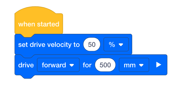
- While the area is being set up, one or two members of your team should create a new project named Momentum. Set the velocity at 50% and have the Speedbot drive forward to the first line at 50 cm. Keep in mind 1 cm = 10 mm, so the robot will travel forward for 50 cm or 500 millimeters.
![]() Teacher Toolbox
-
Why this activity?
Teacher Toolbox
-
Why this activity?
Data collection and analysis, even simple pattern recognition, are fundamental science skills. This activity adds structure to that data analysis by preventing common missteps. Notice that the instructions do not tell students to vary the driving distance of the robot along with varying the velocity of the robot. This is an intentional application of what learning scientists call the Control of Variables Strategy. Teaching novice investigators to manipulate one variable at a time (i.e., the velocity in this case) to determine its influence on a second variable (i.e., the distance the ball travels after collision) is important because it is not necessarily an approach students will adopt spontaneously over a guess-and-check approach. Typical guess-and-check approaches often manipulate more than one variable at a time (i.e., changing both the velocity and the distance the robot travels) and observing the confluence's impact on the distance the ball travels after rotation. This activity tries to guide students away from that because the relationships between the variables are then ambiguous. Is it the higher velocity of the robot, the farther distance the robot drives, or both that lead the ball to travel farther? We can't answer that when we manipulate both variables at the same time.
However, teams might spontaneously try driving the robot different distances. If you observe this, ask them only to change the distance but keep the velocity the same as it was in a trial with the original 500mm distance. That way, they can compare the same velocity with different driving distances to see if the robot's driving distance also factors into how far the ball travels.
Step 6: Testing the Transfer of Energy during Collisions

![]() Teacher Tips
Teacher Tips
-
Prepare the area for the ball to bounce in varying directions for varying distances. Close doors and/or windows as needed.
-
The table for Exploring Velocity can be saved from below, or students can recreate the table in their engineering notebooks.
-
A rubric for evaluating team engineering notebooks can be found here (Google / .docx / .pdf), and a rubric for evaluating individual notebooks can be found here (Google / .docx / .pdf). Whenever you plan to evaluate student work with a rubric(s), be sure to share the rubric with them before they begin to work on the project.
Center the ball on the horizontal line at 50cm and place your robot so that the front of it is centered on the horizontal line at 0cm. Make sure the front of the robot is facing the direction of the ball. Run your first Momentum project that has the velocity set to 50% and pay close attention as the robot collides with the ball.
Record the set velocity, the distance driven, and the distance the ball traveled in this Data Table (Google / .pdf). The first row of the table has been started for you based on the Momentum project you worked on in the previous step. Continue to add data to this table as you try setting different velocities. You can then add other teams' data as you discuss your findings as a class.

Think about and respond to the questions below in your engineering notebook as you collect your data:
- How can you tell that the momentum of the robot transferred energy to the ball during the collision? Explain with details.
- Repeat the test at least twice more. Try a velocity less than 50%. Reset the ball in its position and record in the table how far the ball travels. Also, try a velocity more than 50%. Reset the ball in its position and record in the table how far the ball travels.
- When all groups have completed their three tests, discuss the velocities that the other groups chose and how far the ball traveled in their tests. As teams share their data, add their findings to your table.
- Look for pattern(s) in the data. Does the distance traveled by the ball increase or decrease as the set velocity increases?
![]() Teacher Toolbox
-
Answers
Teacher Toolbox
-
Answers
-
The movement of the ball is evidence that the robot transferred energy during the collision. Students might also describe the speed of the ball after impact or its direction of travel as evidence.
-
The distance that the ball travels depends on the mass/weight of the ball used and the velocity set for the robot.
-
Students should recognize that higher velocities lead the ball to travel farther than lower velocities. Explicitly connect this to the momentum of the robot. Highlight that the weight of the robot has not changed, only its velocity but that both contribute to the robot's momentum. Ask them if they think the ball would travel as far if the robot was heavier. It presumably would. There is more about the effects of the mass of the ball during the collision in the next reading.
-
Student groups might have selected widely variable velocities but the overall learning objective is for students to recognize that higher velocities lead to greater momentum which transfers more energy to the ball during collisions.