Moving the Arm
Once you understand where you want to move the arm on the Workcell and know that it will meet the mechanical needs of your build, you can get ready to move the arm. This page will provide steps for moving the arm from one location to another on the Workcell and some tips to keep in mind.
Removing the Arm
Ensure that the Brain is off. You can do this by holding down the power button on the Brain or by unplugging the Battery.
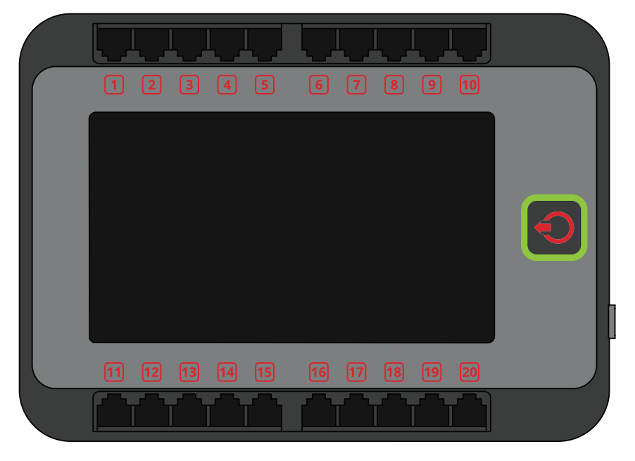
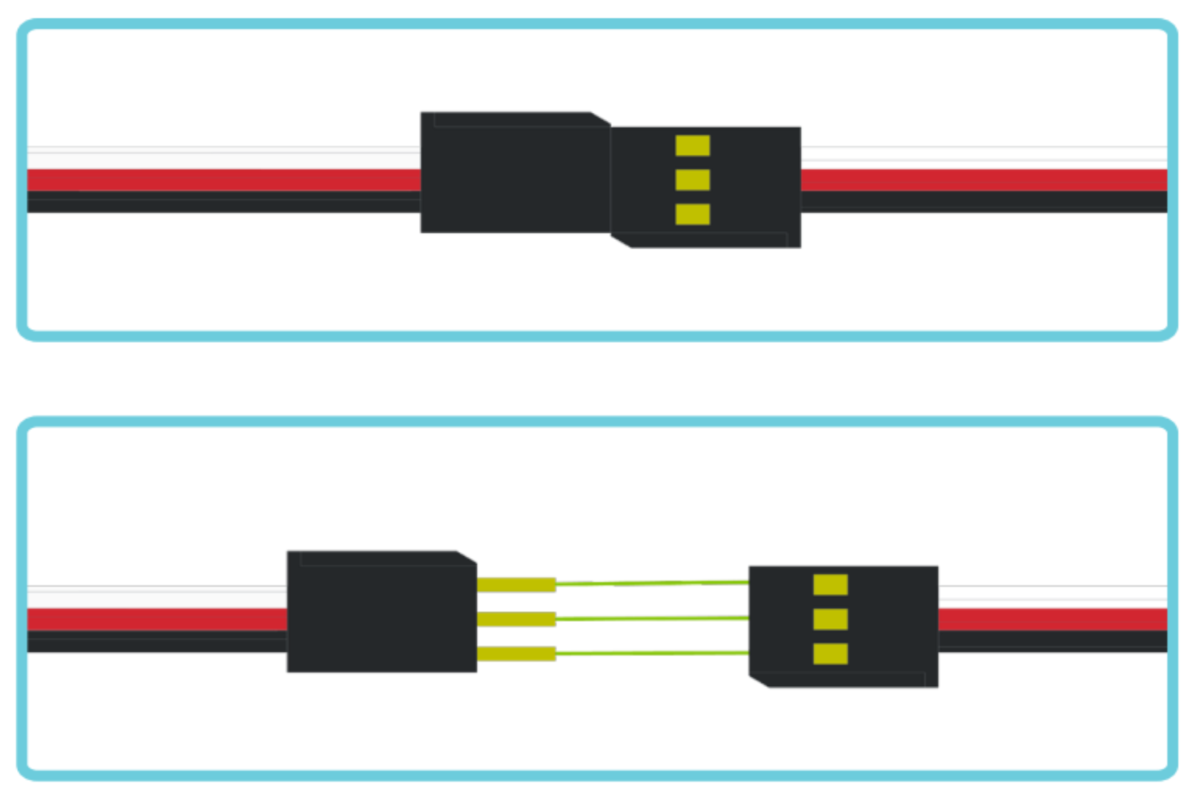
Unplug all 3-wire cables, 3-wire extension cables, and smart cables. This removes any dangling pieces from your build that could get tangled or caught while moving the arm to its new location.
Ensure that all of the cables are labeled before removing them from their associated ports. This ensures that you can connect the correct wires to the correct ports when attaching the arm back onto the base plates.
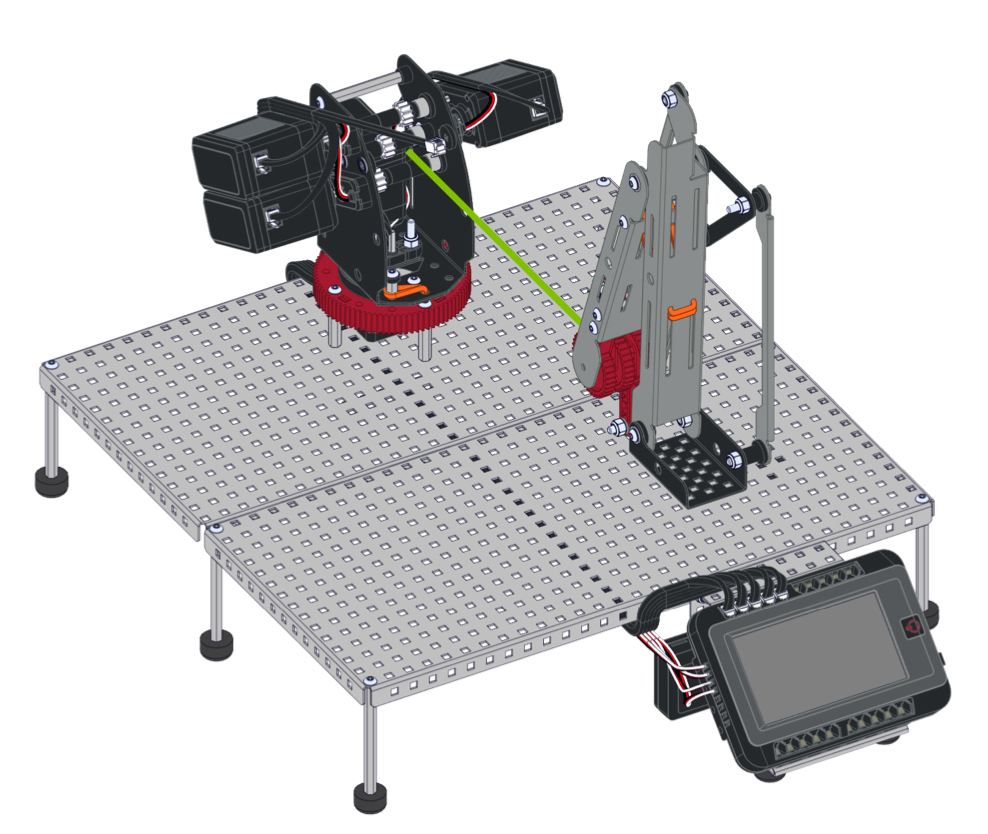
Remove the mastering jig if it is in the build and detach the arm from the base and turntable.
Make sure to set the arm carefully to the side until you are ready to reattach it. Also set aside the two spacers, shaft, and shaft collars that will be loose from removing the arm.
You may have to remove some rubber bands in order to remove the arm.
Unscrew the four star drive screws that attach the turntable to the base plate and slowly lift the base and turntable off of the base plate.
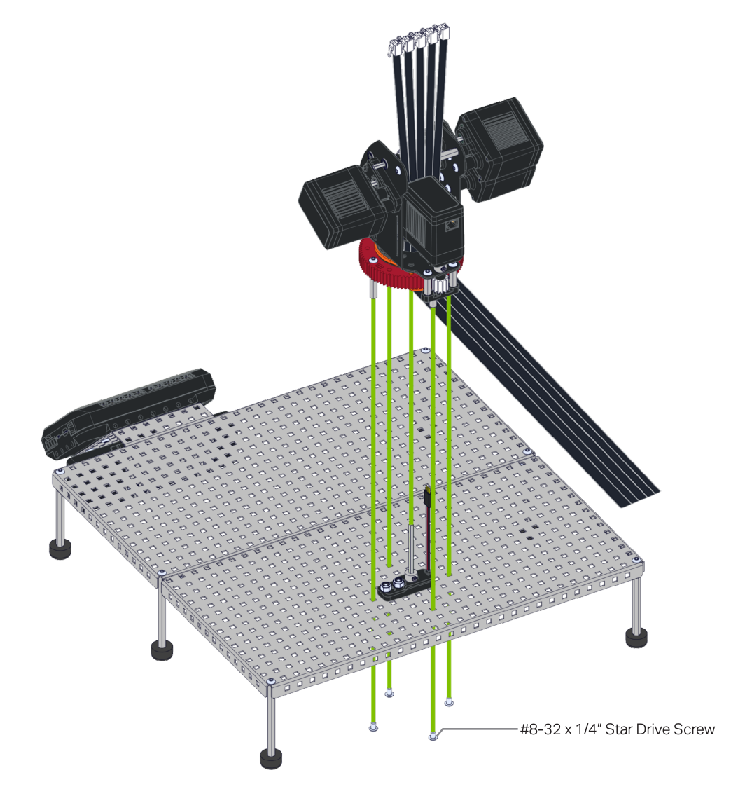
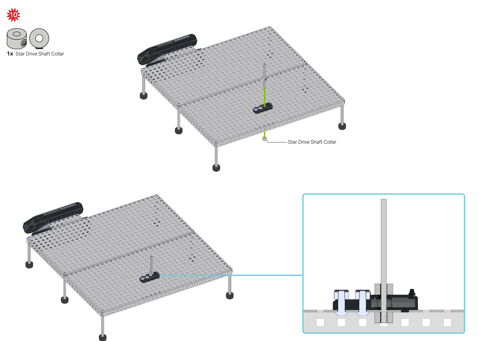
Remove the shaft from the potentiometer by first removing the shaft collar from the underside of the base plate and sliding the shaft up. The shaft collar to remove is marked here.

Also remove the potentiometer from the base plate.
Adding the Arm
Before adding the arm back to the Workcell, ensure you know where the arm needs to be placed. This placement should be based on the positions the arm must end up in and will affect the coordinate system of the Workcell once placed.
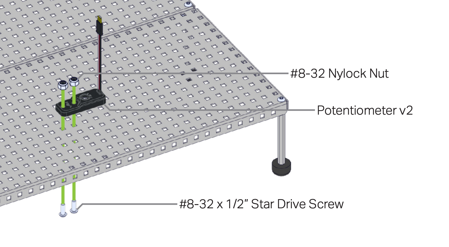
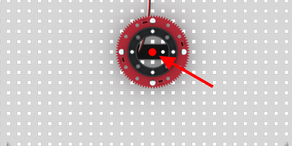
Place the Potentiometer on the base plate at the desired location. Remember the (0, 0, 0) point of the Cartesian Coordinate System will be wherever the center of the turntable is (also where the shaft that goes into the Potentiometer), as shown in the image here.
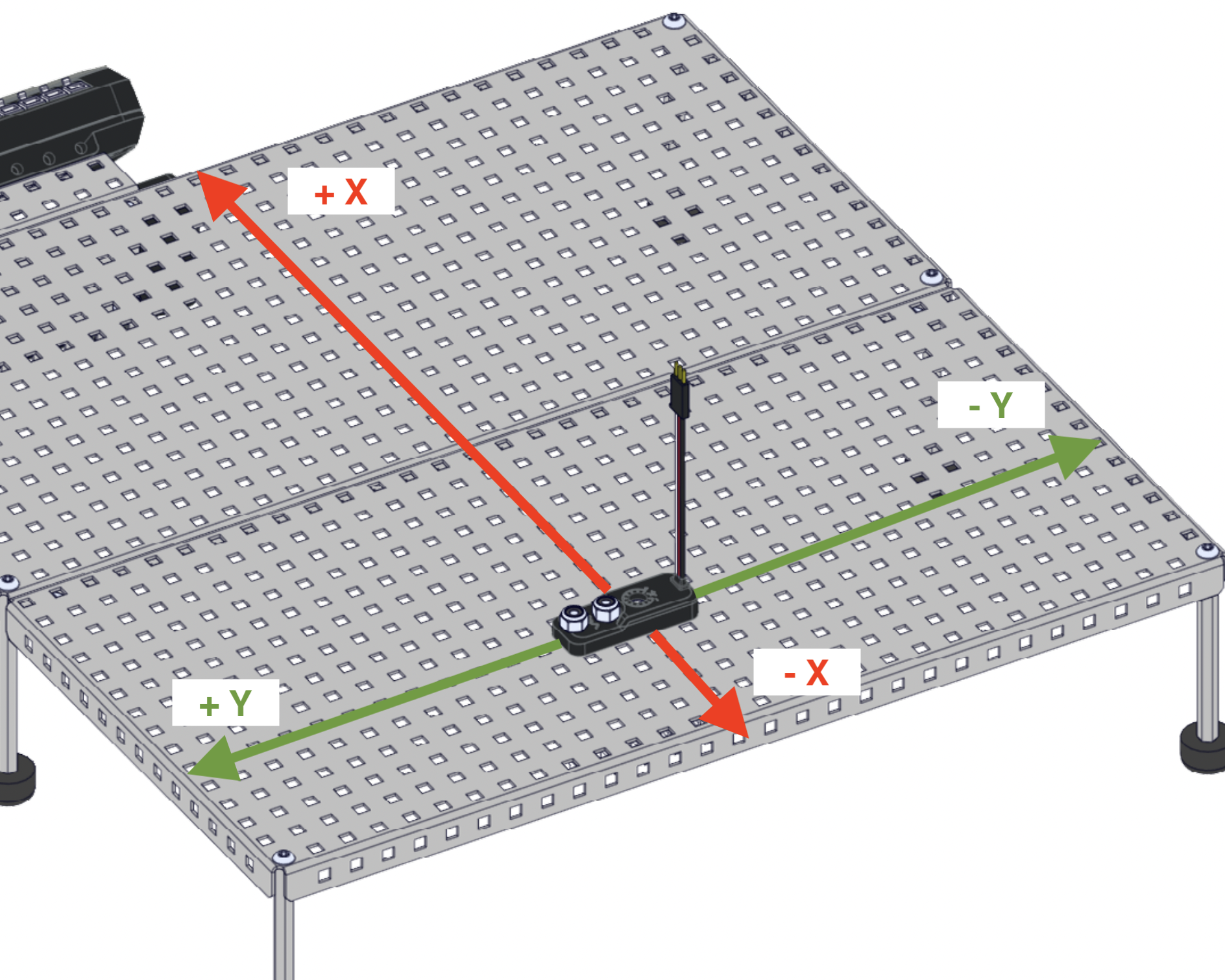
When looking at the Potentiometer, remember the orientation. The direction of the screws on the Potentiometer will align with the positive y-axis and the direction with the 3-wire cables will align with the negative y-axis.
Attach the potentiometer to the base plate in the location that will work best for your design.
Keep in mind that this image is just an example of how attaching the potentiometer could look. Each group's Workcell design and layout may look different.
For additional support, follow steps 8-10 in the Lab 1 build instructions.
Add the base of the arm back to the Workcell. Ensure that the orientation of the base matches the desired orientation of the arm.
For additional support, follow step 33 in the Lab 1 build instructions.
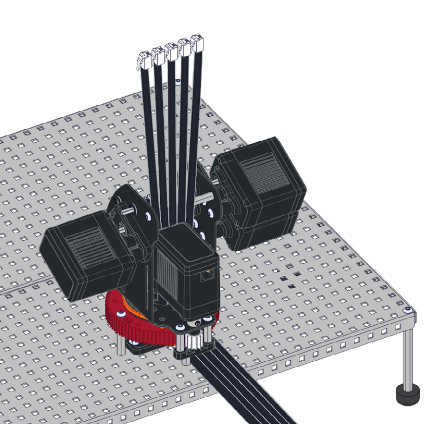
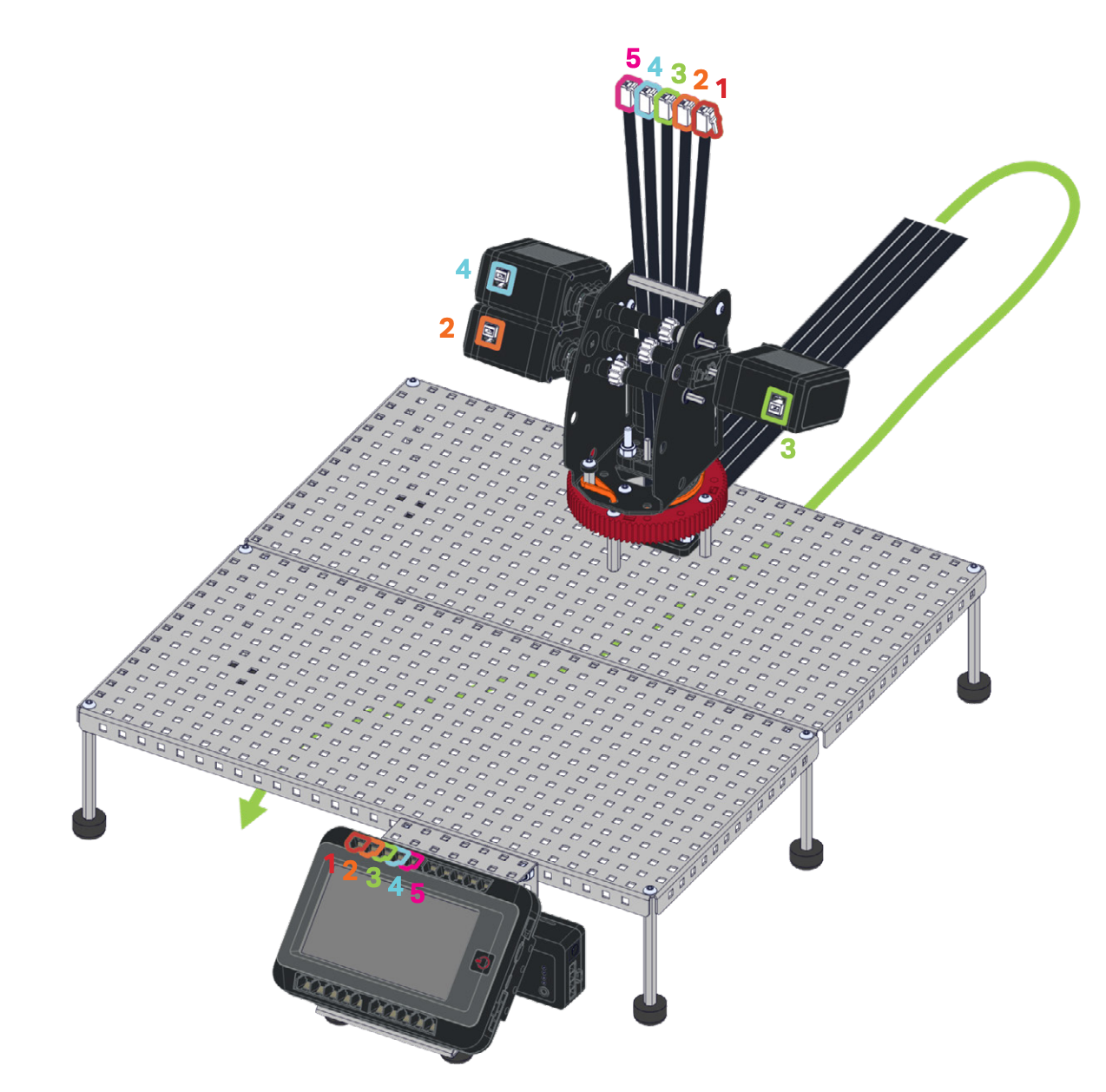
Reattach all of the cables to the smart motors and sensors.
Note that you may need to use different lengths of cables than what is listed in the build instructions or you can create your own custom length smart cables. See the following page to learn more about creating custom cables.
For reference on which ports the motors should be attached to, view steps 34 and 35 of the Lab 1 build instructions.
Use the Arm Install example project to master the arm.

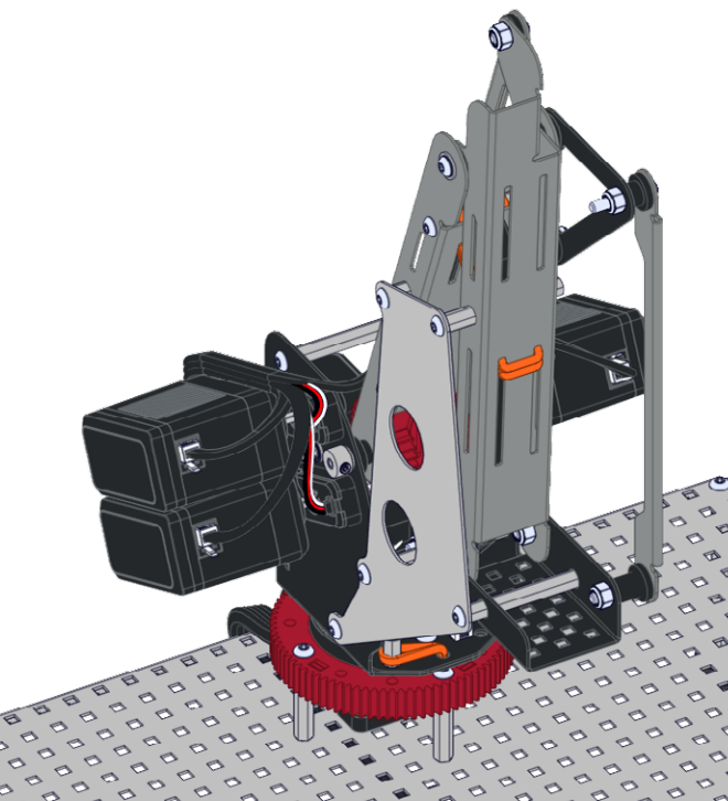
Reattach the arm and add any needed rubber bands.
View this article for helpful hints on how to install the rubber bands.
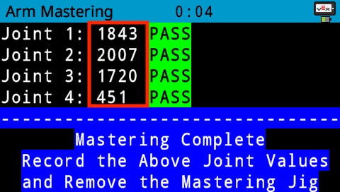
Record the mastering values using the Seek Checklist V5 Workcell - Lab 13 - Workcell Capstone Project now that the arm has been physically moved from one location on the base plate to a new location.
View the Mastering Values page from the Seek section for additional information.
