Cartesian Coordinates
As you get ready to design your Workcell for the Capstone Project Competition, you have to consider how to code the arm to move to specific locations, such as the Start and End Zones, autonomously. In order to code the arm of the Workcell for autonomous movements, you have to understand the arm’s reachability and the associated (x, y, z) coordinates that the arm will move to. The overlay of the coordinate system changes depending on the location of the arm, and is crucial to understand in order to code the arm to pick up and place disks. Understanding how the Workcell and its arm moves in 3D space was covered in Workcell Lab 3’s Play section.
However, what will the coordinates be if the arm was moved to a new location on the Workcell? On this page in the Play section, you will explore the Cartesian Coordinates of a moved Workcell arm.
Workcell Orientation Activity
As you read through the page, complete the following activity to practice understanding the orientation of the Workcell and how the Cartesian Coordinate system is related to the orientation:
- Sketch a placement for the arm of the Workcell in addition to the Start and End Zones.
- Label the approximate X, Y, and Z-coordinates of the Start and End Zones on your sketch depending on the orientation and placement of the arm.
- Use this image from the Capstone Project Competition rules document (Google / .docx / .pdf) to plan out your layout ideas.
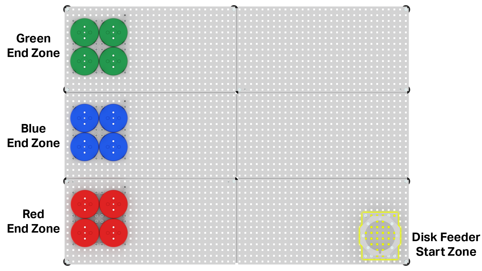
Note: Orientation is the physical position or direction of an object relative to other objects in its surroundings. Remember to think about the placement of the arm relative to the Start and End Zones to determine its orientation.
Cartesian Coordinates of a Moved Workcell Arm
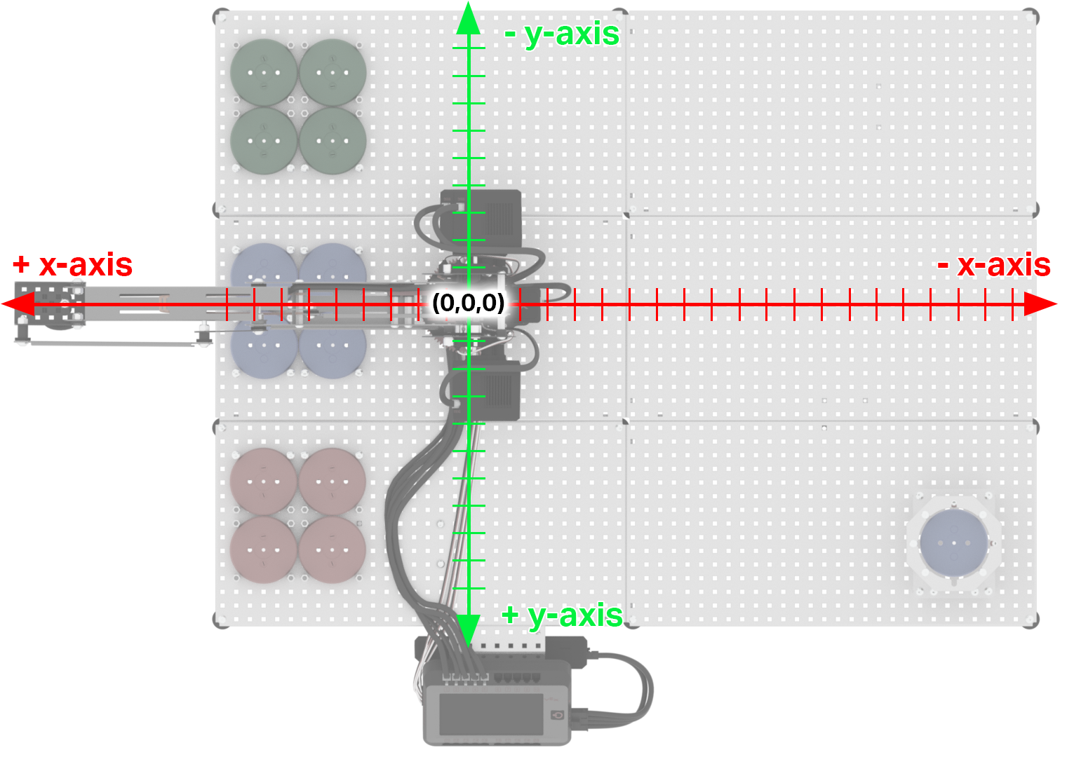
As mentioned in Workcell Lab 3, the (0,0,0) location is found at the center base of the turntable, and is measured to the center of the tool plate on the end of the arm.
This means that the origin is located wherever the center of the turntable is.
If the arm, and more specifically the turntable, is moved from its current location on the Workcell to a new location, the (0,0,0) location also changes.
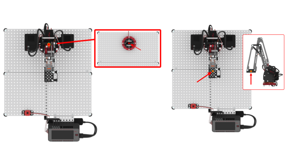
For example, you can see that the origin is still located in the center of the turntable, even though the location of the arm has moved. Furthermore in this image, each tick mark on the X and Y-axes represents one inch.
This is important, because the X, Y, Z-coordinates that the arm can extend depend on the actual location of where the arm is mounted. This means that the coordinate system changes if the placement of the Workcell arm is moved.
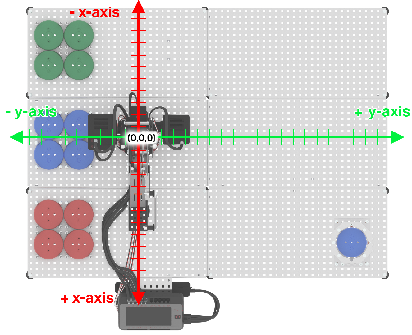
The orientation of the turntable, more specifically the potentiometer inside the turntable, is what designates the coordinate system.
Rotating the potentiometer will change which direction the X and Y-axes face.
In this example, the arm, and more specifically the potentiometer, are facing the V5 Brain. This orients the positive X-axis towards the V5 Brain.
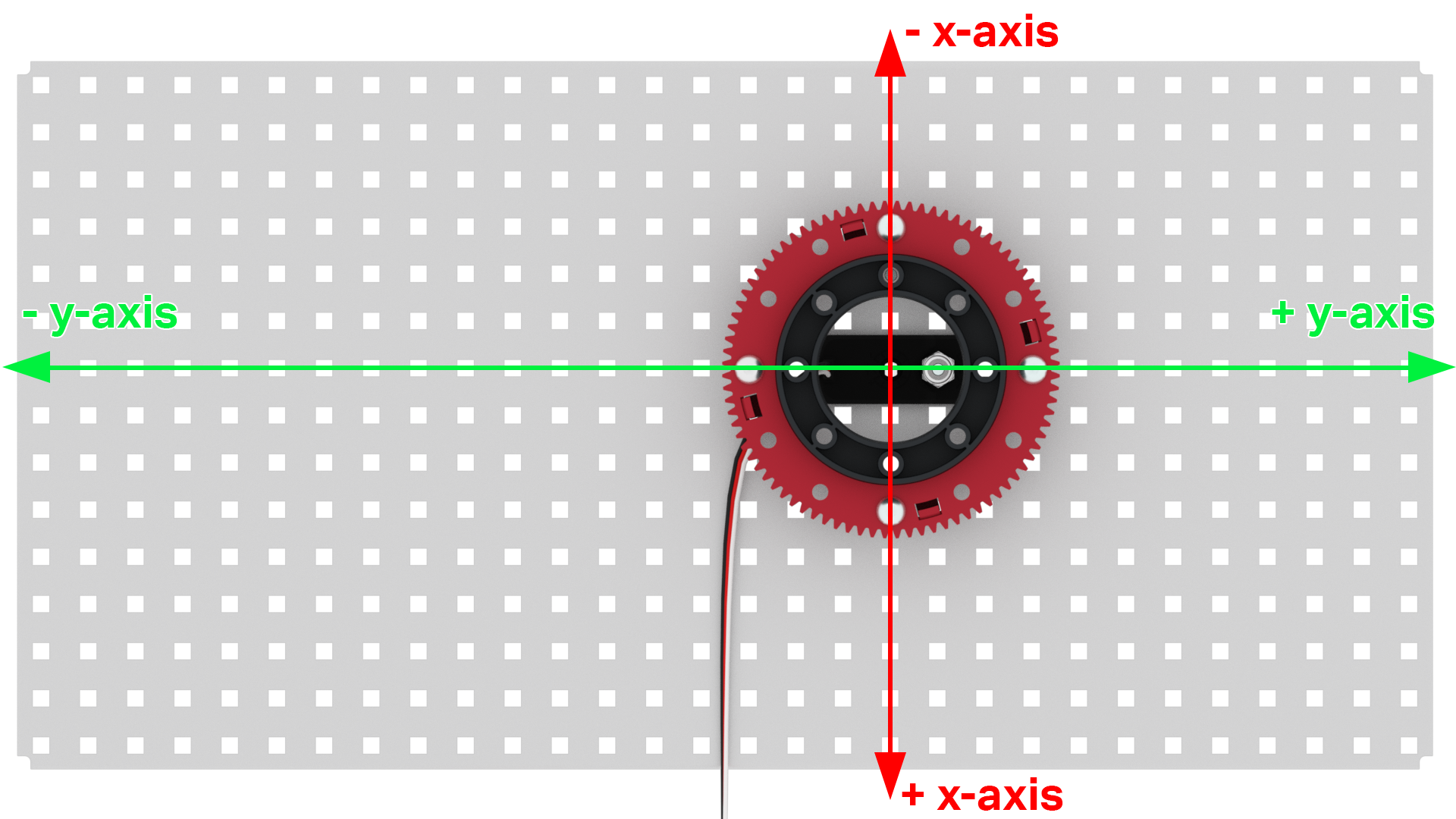
In this example, when the arm is rotated 90 degrees, the potentiometer also rotates 90 degrees.
This orients the positive X-axis towards the End Zones.
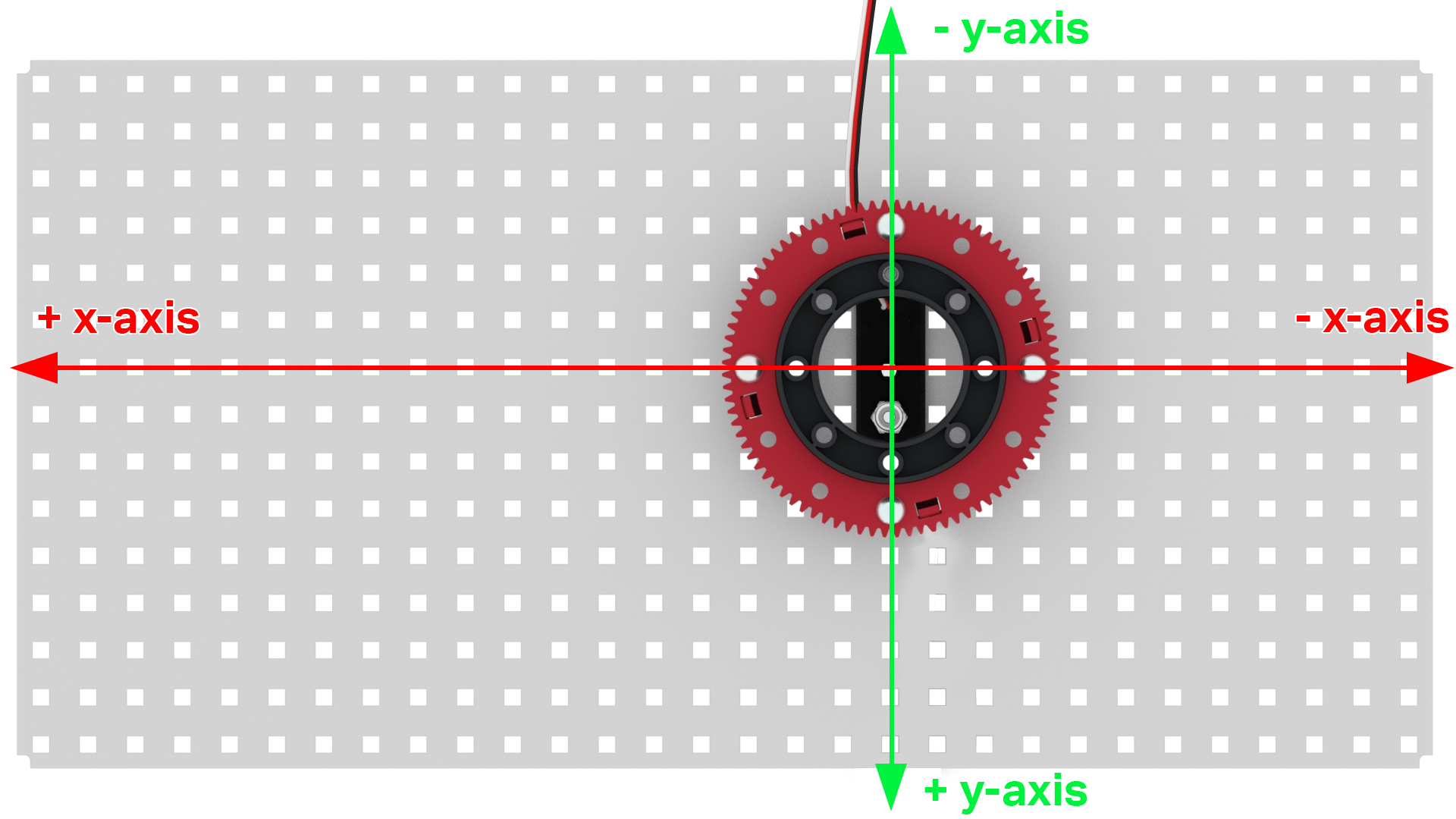
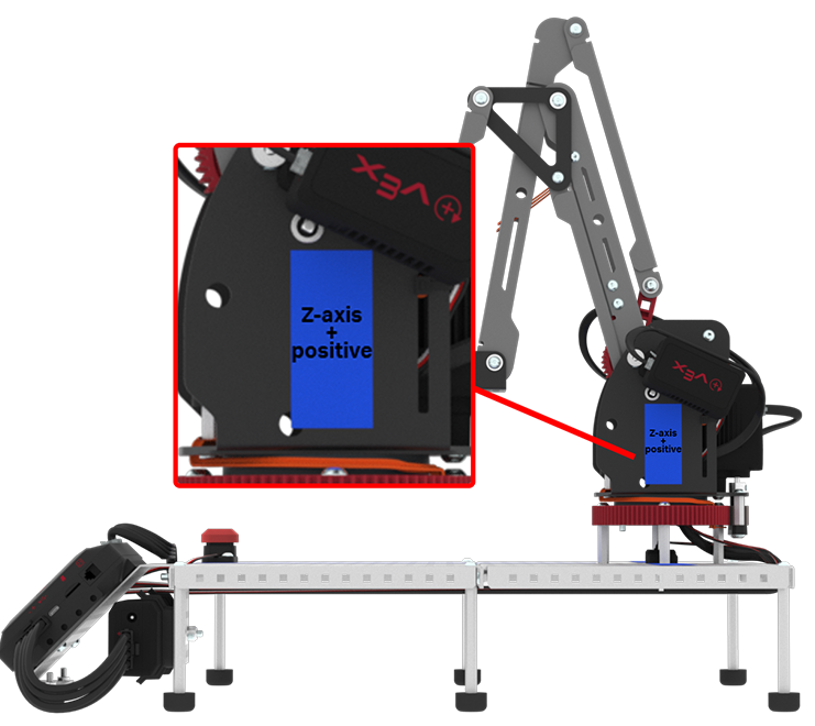
The Z-axis always remains the same no matter where the position of the arm is mounted on the Workcell.
This is because the Z-axis is 0 when the tool plate is touching the base plate of the Workcell.
The positive Z-axis is above the base plate and the negative Z-axis is below the base plate.
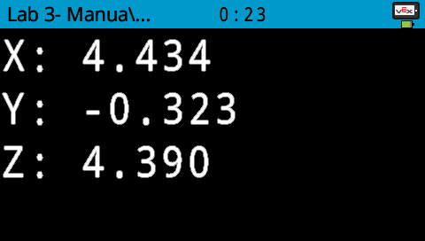
When planning out where elements will go on your Workcell, one helpful piece of information is using the Manual Move example project in VEXcode V5. This example project will display the current X, Y, and Z-coordinate values of the end effector. For more information about this example project or how it works, view Workcell Lab 3’s Play section.
This is helpful to map out the coordinate grid and where certain elements can be placed in order to ensure the arm can reach them.
