
Port Configuration
Port Configuration
Each joint has a Potentiometer and Motor that will need to be plugged into the proper port for the VEX V5 Workcell to work as intended.
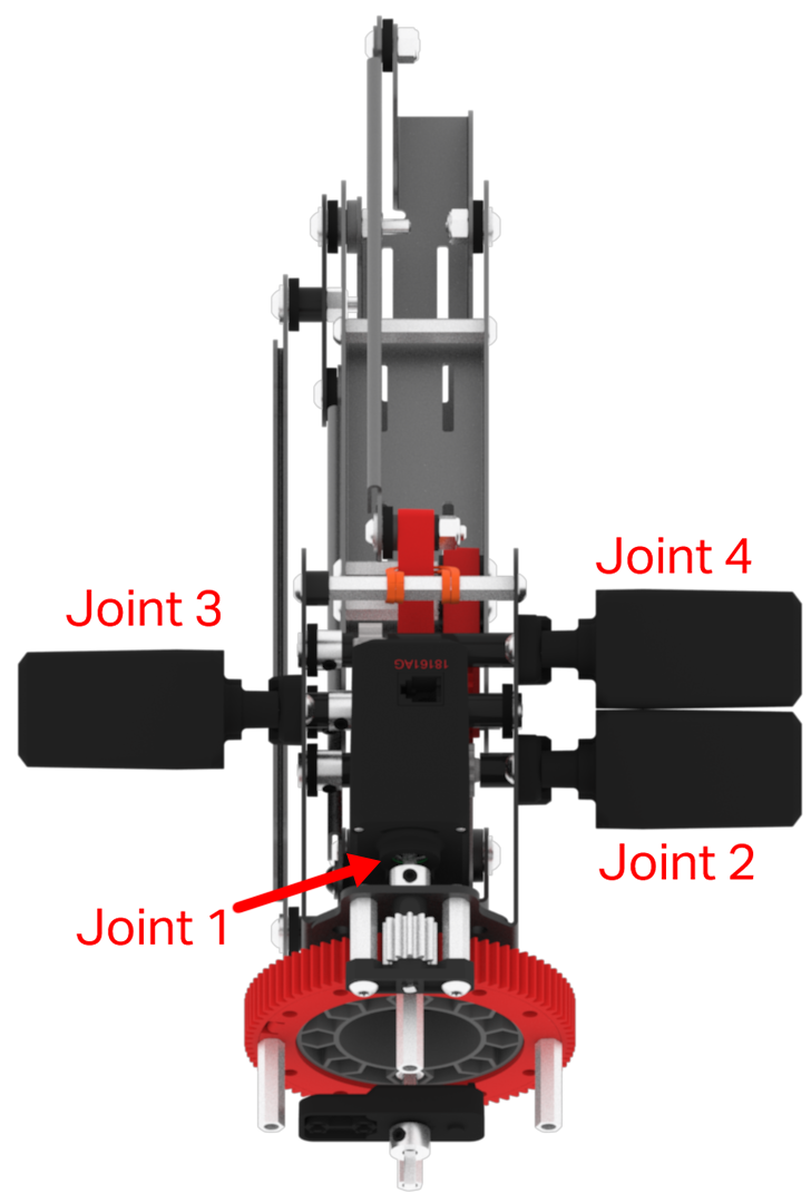
Each joint has a specific port assigned to it. The Potentiometers will go into the lettered, 3-Wire Ports and the Motors will go into the numbered, Smart Ports.
|
Joint Number |
Motor - Smart Port |
Potentiometer - 3-Wire Port |
|---|---|---|
| 1 | 1 | A |
| 2 | 2 | B |
| 3 | 3 | C |
| 4 | 4 | D |
Additional Devices:
- Bumper Switch: 3-Wire Port - E
- Electromagnet: Smart Port - 5
- Optical Sensor: Smart Port - 6
- Intake Conveyor V5 Smart Motor: Smart Port - 7
- Transport Conveyor V5 Smart Motor: Smart Port - 8
- Transport Conveyor Line Tracker Sensor: 3-Wire Port - F
- Disk Pickup Location Line Tracker Sensor: 3-Wire Port - G
- Outtake Conveyor V5 Smart Motor: Smart Port - 9
- Outtake Conveyor Line Tracker Sensor: 3-Wire Port - H
- Disk Diverter: Smart Port - 10
Make Your Own Cables
As you build your V5 Workcell, the standard V5 cables may not be the correct length. To make your own customized V5 Smart Cables, follow the instructions in the Crimping Tool Knowledge Base Article.