
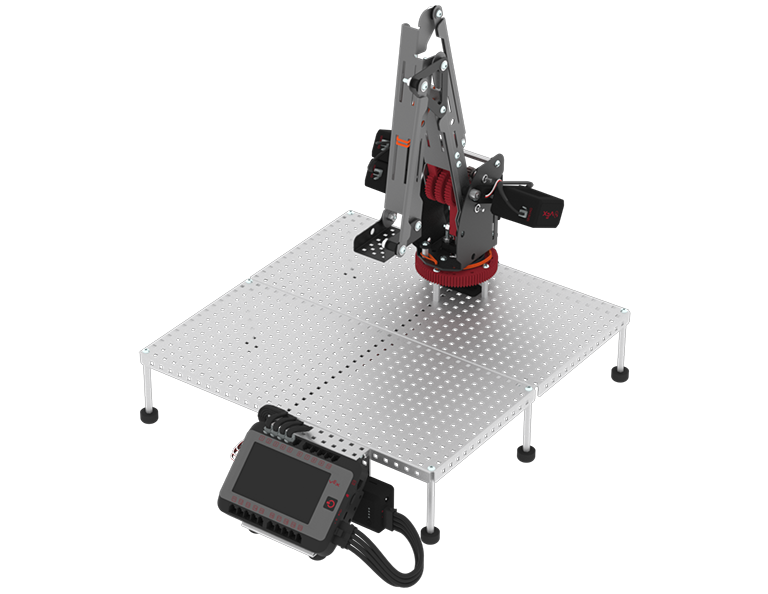
Build Instructions
![]() Teacher Toolbox
-
Building Roles
Teacher Toolbox
-
Building Roles
Before starting the build, consider how your students will be organized. Each student could build a portion of steps from the Build Instructions to allow multiple students the ability to build simultaneously. The Build Instructions can be broken down into the following portion of steps during the building of Lab 1:
- Base plate: steps 1-10
- Left side of the arm base: steps 11-16
- Right side of the arm base: steps 17-19
- Bottom arm base motor and turntable: steps 20 - 31
- Attach the arm base to the base plate of the Workcell: step 32 - 35 (this is recommended to be done by 2 or more students)
- Arm Install example project: steps 36 - 42
- Build the arm: steps 43 - 53
- Build the mastering jig: step 54
- Attach the arm to the arm base: steps 55 - 65 (this is recommended to be done by 2 or more students)
- Add rubber band and the mastering jig: steps 66 - 68
As students are building within their groups, circle the classroom helping groups as needed.
Select the button below for the V5 Workcell Lab 1 Build Instructions.
Port Configuration
As you go through the Build Instructions, you will see that each joint has a potentiometer and motor that will need to be plugged into its assigned port, in order for the arm mounted on the V5 Workcell to work as intended. The breakdown of where to insert each of these cables is covered in the Build Instructions.
If you are using the Standard Config, each joint has a specific port assigned to it (as seen in the table below). If you are using a Custom Config, each joint can be assigned to your desired port. The Potentiometers will go into the lettered, 3-Wire Ports and the Motors will go into the numbered, smart ports.
| Joint Number | Motor - Smart Port | Potentiometer - 3-Wire Port |
|---|---|---|
| 1 | 1 | A |
| 2 | 2 | B |
| 3 | 3 | C |
| 4 | 4 | D |
Measuring and Making Your Own Cables
As you build your Workcell, you may want to make your own customized V5 Smart Cables instead of using the pre-determined sized cables. To do so, follow the instructions in the Crimping Tool Knowledge Base Article. For help with measuring these cuts, as well as measuring many different pieces in the VEX V5 ecosystem, view this article for information on how to Use the Printable VEX V5 Parts Ruler.
Installing V5 Workcell Rubber Bands
Installing the rubber bands on the Workcell is crucial for reliable and repeatable movements of the arm. Think of these rubber bands as the muscle of the Workcell. Installing these rubber bands correctly ensures that your Workcell will function as intended. If you notice that your V5 Workcell’s arm is not moving accurately, shaking, or generally not moving in a smooth manner, the rubber bands may not be installed correctly, or at all. View this article from the VEX Library for helpful tips and tricks, as well as animations for how to install your rubber bands.
![]() Teacher Tips
Teacher Tips
- Do not over tighten nylock nuts on pivot points.
- Do not over tighten screws into the V5 Smart Motor #8-32 Threaded Inserts. This could damage the inserts.
- Ensure shafts are fully inserted into the shaft socket of the V5 Smart Motors.
- When inserting shafts, use the handle of the screwdriver or the flat surface of the open ended wrench when applying pressure.
- When handling rubber bands, ensure to not stretch them beyond their limits, they may snap.
For more tips and guidance when building, go to the V5 Workcell Educator Certification.