
In the previous Lesson, you learned about relative movement and how it compares to absolute movement. As you went through the Lesson, you were asked to make predictions about how the 6-Axis Robotic Arm would move when a project was run. This is an example of reading code.
In this Lesson, you will practice code reading to determine what will happen when a project is run.

What is Code Reading?
Just like writing code, reading code is a fundamental skill for programmers. Programmers often need to read and understand code written by others, whether to fix problems in the code, review code, or learn from existing projects. You have read code each time you have looked at a project and made a prediction about what it will do in your engineering notebook. Now you are going to practice this skill more intentionally. In the projects in this Lesson, it will be important to look at whether the code is using absolute or relative movement and how this impacts what is drawn on the Whiteboard Attachment.
Organizing Your Code Reading
There are many tools that can be used to help you determine what will happen in a project. Using your engineering notebook to visualize the behaviors of the robot can be a helpful tool to get started reading code.
This Lesson will show one way to organize code reading in your engineering notebook. You can use the layout shown here as a starting point as you work through describing each part of your project. In the examples in this Lesson, the engineering notebook page has an image of the VEXcode project on the left, with the lines for adding text on the right. In each step, the blocks that are being focused on are highlighted with a red box, and the text describes the behavior(s) associated with those blocks.
Reading the Code in Project A
To practice code reading, we will walk though the documentation process as we read the code for Project A.
Document this project in your engineering notebook. This can be done by writing the steps out in sequence or by adding the image of the code directly to your notebook.
Before beginning the steps to read the code, make a prediction about what the 6-Axis Arm will do when the project is run. You will return to this prediction after completing this code reading process.
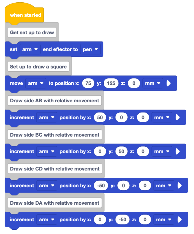
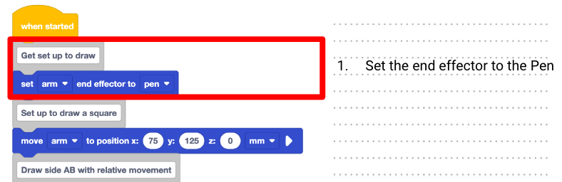
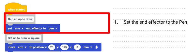
To read code, start at the beginning of the project. Looking at the first block, write the behavior associated with that block in your engineering notebook, beside the project.
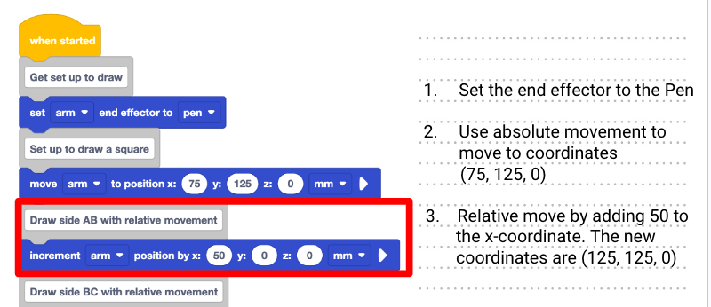
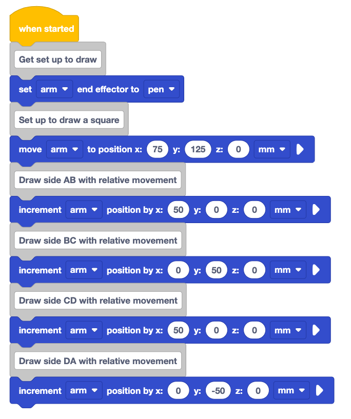
Here, the first blocks can be described as: 1. Set the end effector to the Pen.
As you read the code, you will need to look closely at each block to determine if the 6-Axis Arm will be using absolute or relative movement.
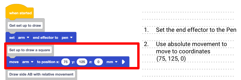
In this project, the first movement block is a Move to position block. Note that the 6-Axis Arm will use absolute movement to move to the coordinates listed in the parameters of the block.
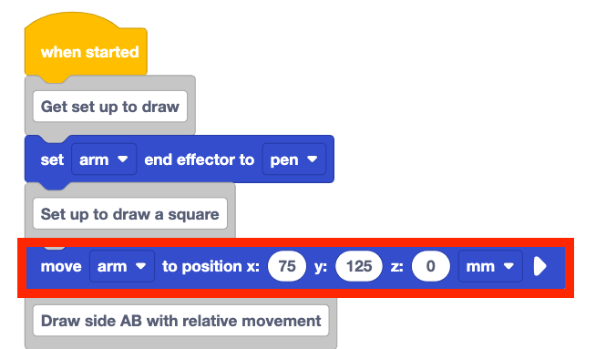
Record the behavior associated with the block in your engineering notebook. This comment and move to position block can be described as: 2. Use absolute movement to move to coordinates (75, 125, 0).
Look at the next movement block in the project. Is this an absolute or relative movement?
This is an Increment position block, so it indicates relative movement by the 6-Axis Arm.
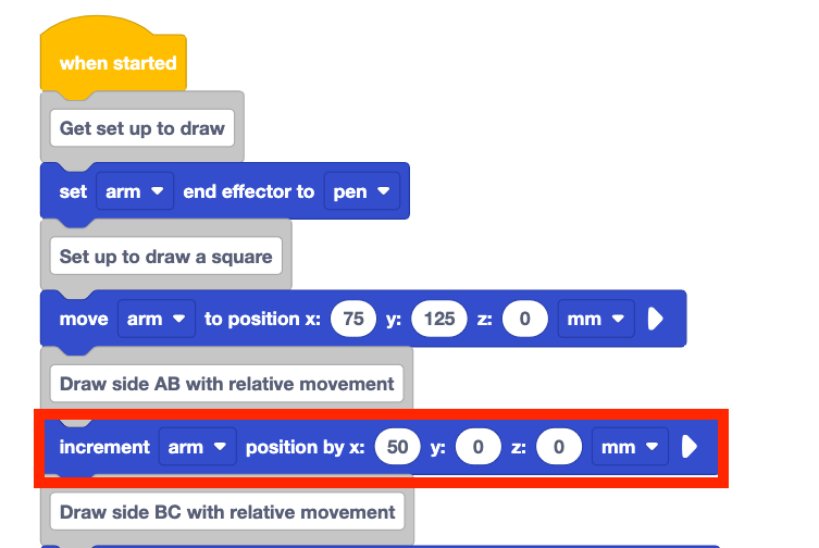
Use the increment provided in the parameters of the block to determine the position where the 6-Axis Arm will be moving when this block is executed. Do this by adding the value of the relative movement (50mm) of the matching coordinate (x) from the absolute movement block.
Record this in your engineering notebook. This could be described as: 3. Relative move by adding 50 to the x-coordinate. The new coordinates are (125, 125, 0).
Continue this process for the remaining blocks in the project. Document what each block will do when the project is run.
Remember to read Comment blocks and Notes for reference when reading the project.
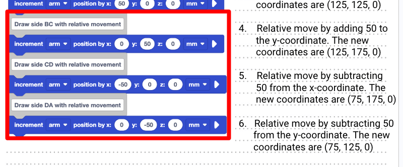
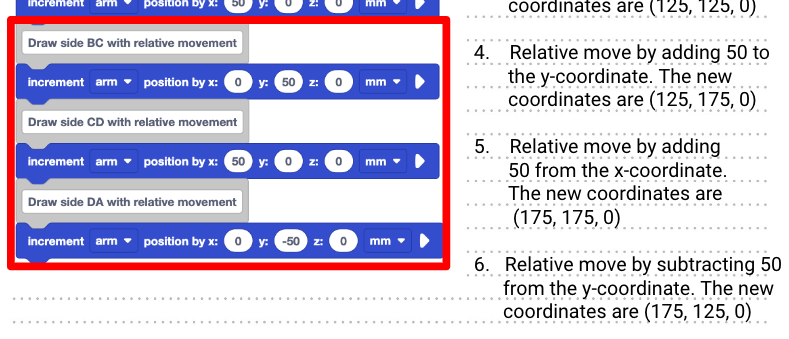
The remaining steps of this project to draw the remaining three sides could be described as follows:
4. Relative move by adding 50 to the y-coordinate. The new coordinates are (125, 175, 0).
5. Relative move by subtracting 50 from the x-coordinate. The new coordinates are (75, 175, 0).
6. Relative move by subtracting 50 from the y-coordinate. The new coordinates are (75, 125, 0).
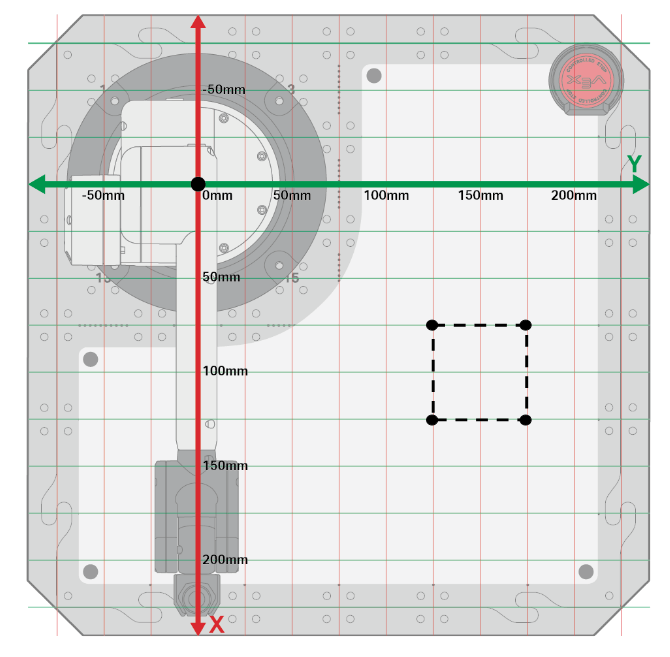
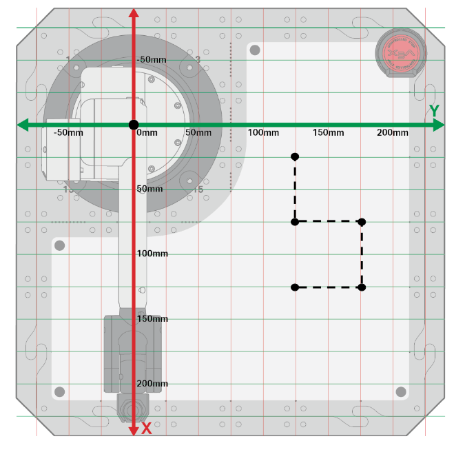
Sketch the path of the 6-Axis Arm when the project is run.
To help visualize the final product of the project, use the coordinates you determined to sketch the path in your engineering notebook.
Watch the project being executed. Answer the following questions in your engineering notebook.
- How do the observed behaviors of the 6-Axis Arm compare to your list of behaviors in your engineering notebook?
- How does your list of behaviors compare to the prediction you made at the start of the Lesson?
- How does the prediction you made at the beginning of the Lesson compare to the behaviors shown in this video?
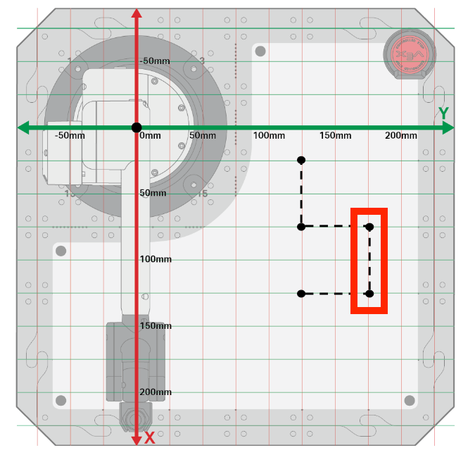
- In the video below, the 6-Axis Arm moves from the safe position to place the Pen at location (75, 125, 0). It then moves away from the base to draw the first side of the square, to the right to draw the second side, toward the base to draw the third side, and to the left to complete the square.
Congratulations! You have now read code and used that knowledge to determine what happens when a project is run. You will continue to practice this with two additional examples.
Reading the Code in Project B
In this example, you are going to practice reading code in order to find a mistake in a project. The intention of this project is to draw a square, just as in Project A. However, if Project B was run, the 6-Axis Arm would not draw a square as intended. You will read the code in this example by following the same steps you used in Project A in order to find the error. Then you will use the information from our code reading to identify how the problem can be fixed.
Document the project in your engineering notebook. This can be done by writing the steps out in sequence or by adding the image of the code directly to your notebook.
Make a prediction about what the 6-Axis Arm will do when the project is run. You will return to this prediction after completing this code reading process.
Start at the beginning of the project. Document the project setup blocks just as you did for the previous project.
The first comment and set end effector block could be described as:
1. Set the end effector to the Pen
Read the first movement block in the project, paying attention to whether the movement is absolute or relative. What behavior would the block cause the 6-Axis Arm to complete? Visualize this behavior.

Record the behavior you visualized for this block in your engineering notebook.
This behavior could be described as:
2. Use absolute movement to move to coordinates (75, 125, 0).

Now look at the second movement block. Is this an absolute or relative movement? This is an Increment position block, so it indicates relative movement by the 6-Axis Arm.
Visualize the behavior this block would cause the 6-Axis Arm to complete.

As you did for Project A, read the parameters of the block to determine where the 6-Axis Arm's position will be after the Increment position block is executed. Record this in your engineering notebook.
This comment and the increment position block could be described as:
3. Relative move by adding 50 to the x-coordinate. The new coordinates are (125, 125, 0).

Continue this process for the remaining blocks in the project. Visualize then document what each block will do when the project is run.
The remaining steps in the project could be described as:
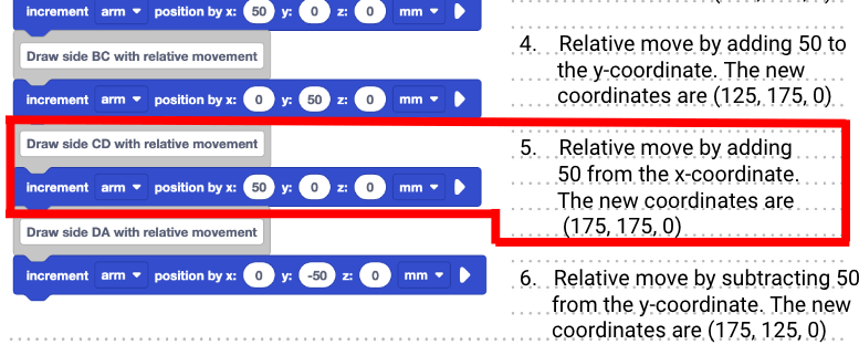
4. Relative move by adding 50 to the y-coordinate. The new coordinates are (125, 175, 0).
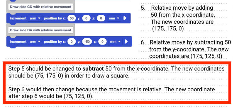
5. Relative move by adding 50 to the x-coordinate. The new coordinates are (175, 175, 0).
6. Relative move by subtracting 50 from the y-coordinate. The new coordinates are (175, 125, 0).
Sketch the path of the 6-Axis Arm when the project is run.
To help visualize and document the final product of the project, use the coordinates you determined to sketch the path in your engineering notebook.
Watch the project being executed. Answer the following questions in your engineering notebook.
- How do the observed behaviors of the 6-Axis Arm compare with your list of behaviors in your engineering notebook?
- How does your list of behaviors compare to the the prediction you made at the start of the Lesson?
- How does the prediction you made at the beginning of the Lesson compare to the behaviors shown in this video?
- In the video clip below, the 6-Axis Arm moves from the safe position to coordinate (72, 125, 0). It then moves away from the base to draw the first side, to the right to draw the second side, further away from the base to draw the third side, and to the left to draw the fourth side.
Now return to your sketch. Identify the step at which point the project stopped drawing a square. As the 6-Axis Arm executes the first three movement blocks in the project, it seems as if the Pen will continue to draw a square.
However, on the fourth movement block, the 6-Axis Arm travels in the opposite direction than expected – along the positive x-axis rather than the negative x-axis. Locate this step in the project and mark it in your engineering notebook.
Now identify the block in the project that corresponds with the step where the error occurred. Mark the block in your engineering notebook as well.
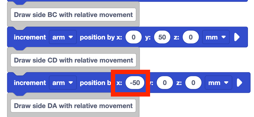
In this example, it is step 5 that aligns with the comment of “Draw side CD with relative movement” that is highlighted.
Apply what you know about movement along the axes to recommend a fix for this error.
In order to draw a square, the 6-Axis Arm needs to move along x-axis in the negative direction. This means that this Increment position block should have the x-parameter set to –50 rather than 50.
Record the change that is needed to make the project run correctly in your engineering notebook.
This could be documented as a note below the project, as described as:
Step 5 should be changed to subtract 50 from the x-coordinate. The new coordinates should be (75, 175, 0) in order to draw a square.
Step 6 would then change because the movement is relative. The new coordinate after step 6 would be (75, 125, 0).
Watch the project run with the x-parameter of the Increment position block changed from 50 to –50. The 6-Axis Arm now moves from the safe position to coordinate (75, 125, 0_, and then moves to draw a square as intended.
Now you have finished reading code for two different projects – one to help you learn a process for reading and documenting code, and another to read code to identify an error in a project. You will continue to practice reading code, visualizing, and documenting projects each time you work with the 6-Axis Arm and VEXcode. You can return to this Lesson at any time to help you remember a process for reading and documenting code.
Activity
Now that you have practiced code reading using two different projects, you will practice again on your own.
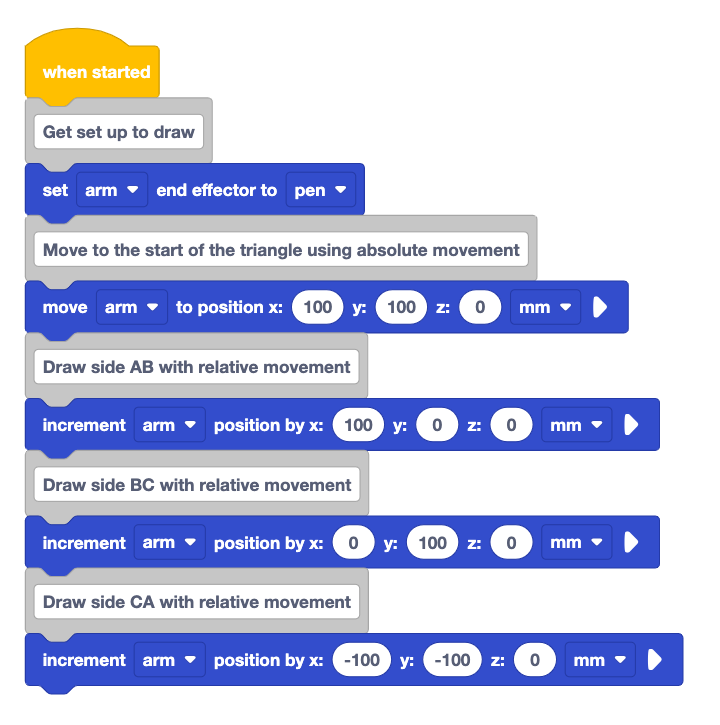
Activity: Follow the procedure you learned to read the code in the project above.
- Document the project above in your engineering notebook.
- Predict what you think the 6-Axis Arm will do when the project is run. Document your prediction in your engineering notebook.
- Read each block in the project, and visualize the behavior the 6-Axis Arm would perform when executing the block. Record this behavior in your engineering notebook.
- Sketch the path the 6-Axis Arm would take when the project is run.
- Check in with your teacher when you are finished. You will watch the project run as a class. Then you will discuss your prediction and documentation.
Check Your Understanding
Before beginning the next Lesson, ensure that you understand the concepts in this Lesson by answering the questions in the document below in your engineering notebook.
Check Your Understanding questions > (Google Doc / .docx / .pdf)
Select Next > to start your Mid-Unit Reflection.