
In the earlier Lessons of this Unit, you used a combination of absolute and relative movements to draw a square. In this Lesson, you will learn about variables and how they can be used to store values in a project. Variables can be used to make projects more efficient.
At the end of this Lesson, you will use variables to draw squares of different sizes.

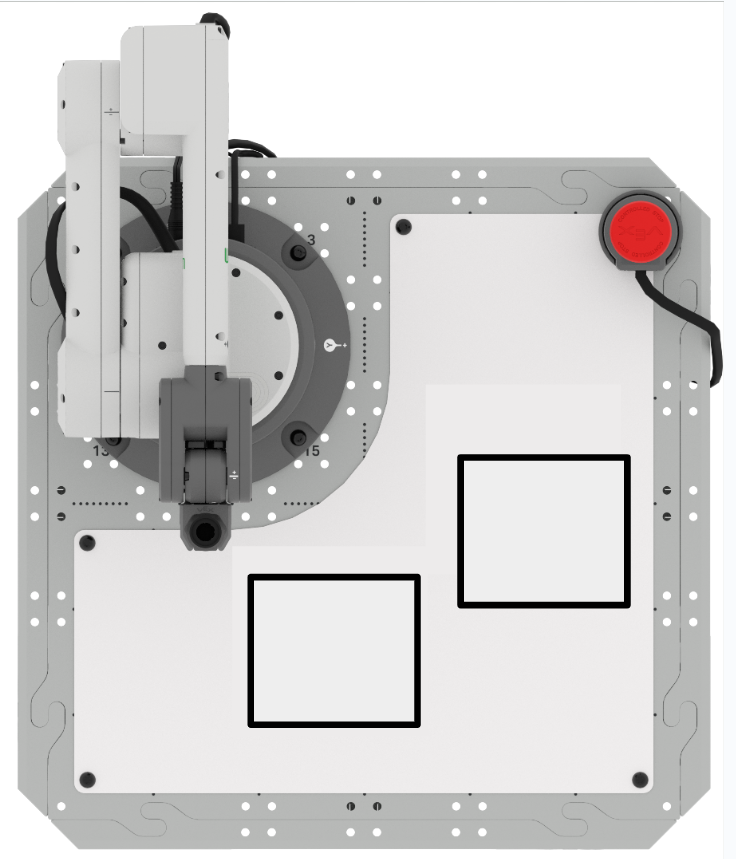
Drawing A Square
Previously, you coded the 6-Axis Robotic Arm to draw a square on the Whiteboard.
Open your VEXcode EXP project from Lesson 1 of this Unit and edit the project to match the one in the image shown here.
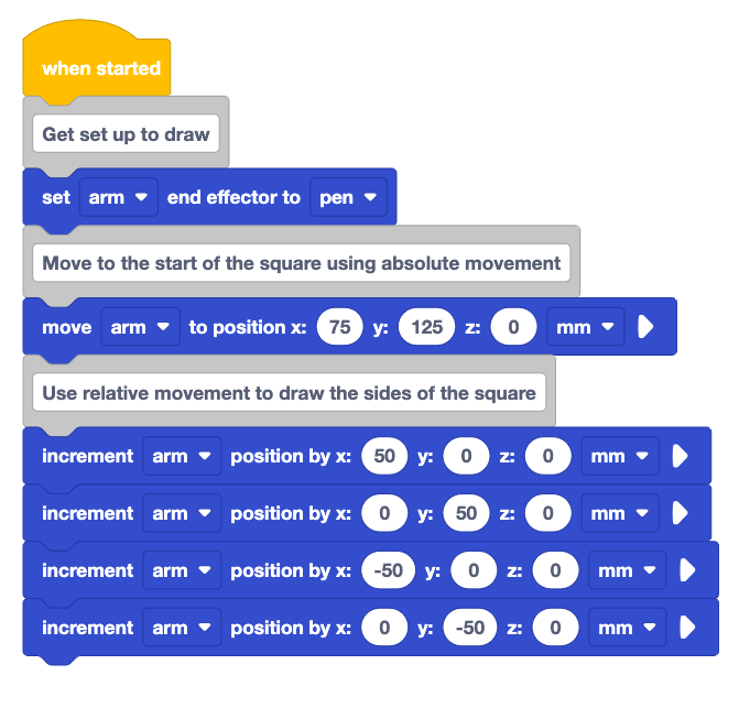
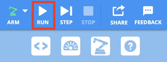
Ensure the 6-Axis Arm is connected to VEXcode EXP and run the project.
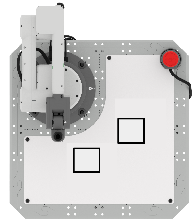
Notice that the 6-Axis Arm draws the square as intended.

Look at the project again. You have parameters that you were repeatedly using (50, 50, –50, –50).
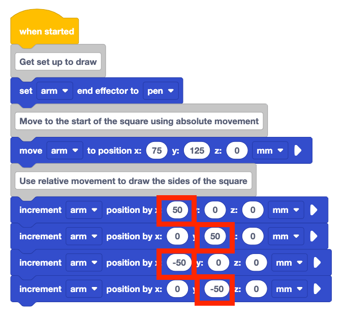
What would happen if you needed to change the size of your square? You would need to type the updated value into every Increment position block. This could lead to possible errors with typing mistakes, forgetting to update a block, or forgetting to add the negative before the parameter.
Instead, you can use a variable to store these values and quickly update them to draw squares of different sizes.
Using Variables
A variable is a way of storing a value to be used later in a project. You will now add a variable to your project to store the value of the side length of the square.
To add a variable, scroll down to the bottom of the Toolbox and select Make a Variable.

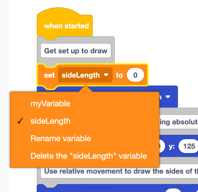
Name your variable "sideLength". Then select Submit.
This variable will be used to store the value of the side length for the square.

The sideLength variable will now appear as a block in the Toolbox.

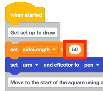
Add the Set variable block to the beginning of your project.
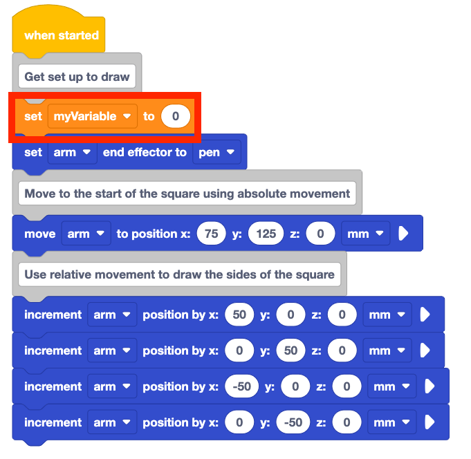
Change the drop-down parameter of the Set variable block from myVariable to sideLength.
Set the sideLength variable to 50 to match the side length of the square being drawn.
50mm is the same side length of the square from the original project.
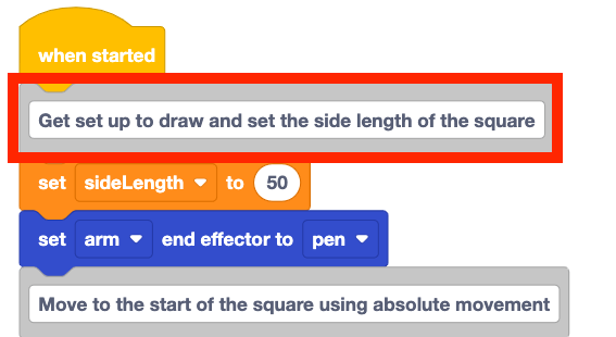
Add to the top Comment block to the project to explain the Set variable block.
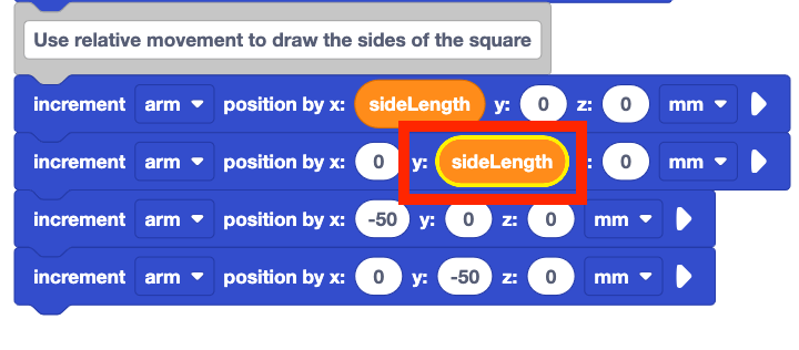
Add the sideLength variable into the first Increment position block. In the video clip, the sideLength variable is selected in the Toolbox, and dragged into the x-parameter of the first Increment position block.
Notice the yellow highlight around the x-parameter when the sideLength variable moves over the Increment position block. This indicates that when the block is released, the block will be added in that parameter. This is because the variable block is a circular reporter block. These blocks will fit in any space that has a circular shape.
Add the sideLength variable to the next Increment position block as the y-parameter.
Notice that the next two Increment position blocks in the project move the 6-Axis Arm in the negative direction.
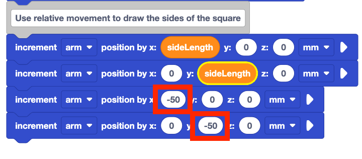
You can use a green Function block with the negative parameter selected in order to use the negative value of a variable in your project. 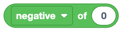
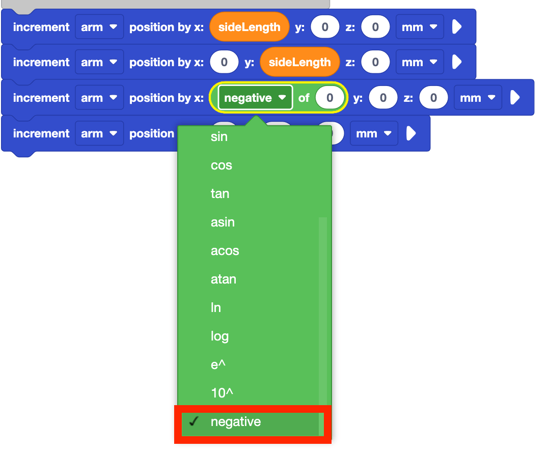
Add the Function block into the x-parameter of the third Increment position block as shown here.
In this video clip, the Function block is selected in the Toolbox, and dragged into the Workspace, and dropped into the x-parameter of the third Increment position block.
Set the dropdown parameter of the Function block to negative.
Add the sideLength variable to the Function block. Now the 6-Axis Arm will move for 50mm in the negative x-direction when the block is executed.

Duplicate this for the y-parameter of the fourth Increment position block.
Remember that you can duplicate blocks by right-clicking to open the Context menu, then selecting "Duplicate Blocks."

Ensure the 6-Axis Arm is connected to VEXcode EXP and run the project.

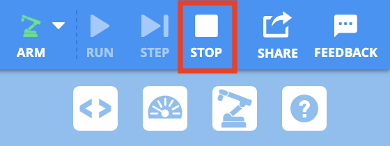
Stop the project after the 6-Axis Arm completes the square.
Note that the square drawn by the 6-Axis Arm is the same as the one created earlier using the Increment position blocks and setting each parameter.
Changing Variable Values
Now that you have created the variable, you can easily change it to another value. This is one of the benefits of using a variable in a project rather than inputting each value separately. You will now practice changing the value of the variable in the Set variable block, then running the project to see the different size squares being drawn by the 6-Axis Arm.
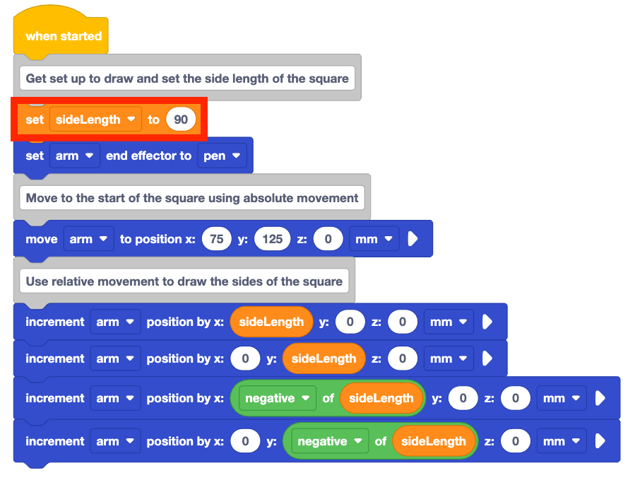
Change the Set variable block from 50 to 90.
What do you think will happen when the project is run? Record your prediction in your engineering notebook.
Run the project.
Do the behaviors of the 6-Axis Arm match your prediction for the project?
The 6-Axis Arm draws a square with side lengths of 90mm. This is because the sideLength variable is set to 90. All of the values in the Increment position blocks are updated to be 90 or –90 because of the variable.
Stop the project after the 6-Axis Arm stops drawing.

Change the Set variable block from 100 to 30.
What do you think will happen when the project is run? Record your prediction in your engineering notebook.

Run the project.
Do the behaviors of the 6-Axis Arm match your prediction for the project?
The 6-Axis Arm draws a square with side lengths of 30mm. This is because the sideLength variable is set to 30. All of the values in the Increment position blocks are updated to be 30 or –30 because of the variable.
Stop the project after the 6-Axis Arm stops drawing.
Be sure to rename and save your project.
Activity
In this Lesson you learned about variables and how to use them effectively in a project to draw a square. Now, you will practice this concept to draw multiple squares of different sizes. 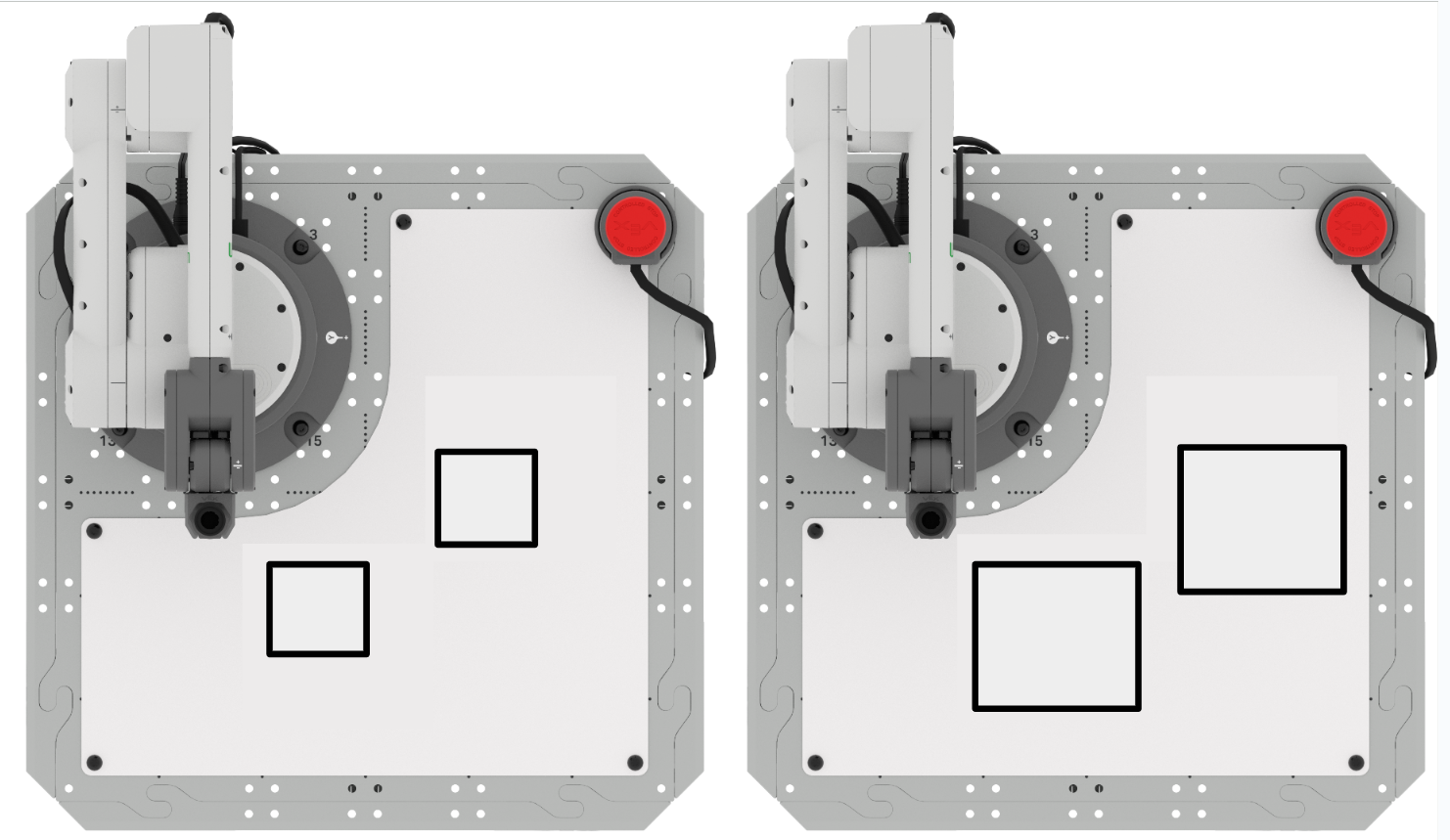
Activity: Edit your project from this Lesson to draw different squares.
- The starting coordinates of the first square are (75, 125, 0).
- The starting coordinates of the second square are (125, 25, 0).
- All side lengths should be 35mm.
Part 1: Build onto your project to draw two 35mm squares.
- Plan how you will build onto your project to draw the squares with your group. Be sure that you are all agreed on your approach before you begin editing the project.
- Edit the project in VEXcode to draw two separate 35mm squares.
- Run the project to test it. Does it draw the squares as you intended? If not, continue to edit the project until you have successfully drawn two separate squares.
Part 2: Edit your project to draw two 70mm squares.
- Plan how you will build onto your project to draw the squares with your group. Be sure that you are all agreed on your approach before you begin editing the project.
- Edit the project in VEXcode to draw two separate 70mm squares.
- Run the project to test it. Does it draw the squares as you intended? If not, continue to edit the project until you have successfully drawn two separate squares.
Pro Tips for this Activity:
- Erase the Whiteboard after each run of your project, so that you can clearly see what the Pen is drawing each time you test your project.
- Practice your code reading skills – Have someone in your group read your code before you run the project. This can be helpful to find any mistakes in the code before it is run, and to be sure that your group has a clear understanding of what the project is intended to do.
Check Your Understanding
Before moving on to the next Lesson, ensure that you understand the concepts in this Lesson by answering the following questions in your engineering notebook.
Check Your Understanding questions > (Google Doc / .docx / .pdf)
Select Next > to move on to Lesson 4.