
In the previous Lesson, you learned about variables and used them in a project to draw different sized squares with the 6-Axis Robotic Arm and the Pen Holder Tool. In this Lesson, you will be introduced to the Repeat block and the Change variable block. You will build onto the project from Lesson 3 to draw four squares of different sizes with the same starting location.
At the end of this Lesson, you will be presented with a project to read. You will sketch what shape you think the 6-Axis Arm will draw, based on the code, in your engineering notebook. You will also determine what the value of the variable will be at the end of the project.

Drawing Four Squares of Different Sizes
Now we are going to build on the project from Lesson 3 to draw four squares of different sizes with the same starting location.
The Repeat Block
A Repeat block is used to repeat the blocks within it a set number of times. The Repeat block saves time and effort while creating projects where blocks repeat. Rather than taking the time to drag in additional blocks or duplicate existing blocks in the workspace, the Repeat block can be used to save space and time.
Open your Unit 6 Lesson 3 project in VEXcode.

Add a Repeat block to the end of your project, as shown in this video. In the video clip, the Repeat block is selected from the Toolbox, dragged into the Workspace and attached to the project, below the final Increment position block.
Drag the Increment position blocks that draw each side of the square into the Repeat block. This will cause drawing all four sides of the square to be repeated.
View this video to see how the blocks should be moved into the Repeat block. In the video clip, the Repeat block is first selected and dragged upwards, and placed beneath the Move to position block. The Comment block reading ‘Use relative movement to draw the sides of the square’ is then selected, and dragged and dropped, with the four Increment position blocks attached, within the C of the Repeat block.
Change the parameter of the Repeat block from 10 to 4. The parameter of the Repeat block is the number of times the blocks inside it will be repeated.
Since we want to draw our square four times, the parameter is set to 4.

Predict how the 6-Axis Arm will move based on this project.
Write your prediction in your engineering notebook, and sketch what you think the 6-Axis Arm will draw when the project is run.

Be sure the 6-Axis Arm is connected to VEXcode. Run the project to test it. (Remember to stop the project when the 6-Axis Arm has finished moving.)
Did the 6-Axis Arm move as you predicted? Why or why not? Document the behaviors in your engineering notebook.

Increasing the Variable
When you tested the project after adding the Repeat block, you noticed that the 6-Axis Arm did draw four squares but they were all the same size. That is because the sideLength variable did not change at any time. To change the size of the square that is drawn, we need to change the value of the sideLength variable. We can change the value of the sideLength variable each time the Repeat block runs. This will change the size of each of the four squares.
The Change variable block will run in each iteration (or repetition) through the Repeat block. By changing the value of the sideLength variable with each iteration, we can create a project that draws four squares that increase in size.
Add a Change variable block to the bottom of the project. In the video clip, the Change variable block is selected in the Toolbox, dragged to the Workspace and dropped between the final Increment position block and the bottom of the Repeat block.
The Change variable block allows a variable to be set to different values in a project. This is helpful as it can change a variable that is used in multiple places within a project.
Set the Change variable block to the variable sideLength and the parameter to 20. In the video clip, the variable parameter is selected, and sideLength is selected from the dropdown menu. Then the value parameter is selected, and 20 is typed in the space.
The parameter is the amount we want to change the value of the variable. In this case, it will change by 20 each time that block is run.
Add a Comment block to the project to explain the intention of the Change variable block. The purpose of the Change variable block in this project is to increase the value of the sideLength by 20mm in each iteration of the Repeat block.

Predict how the 6-Axis Arm will move based on this project.
Write and sketch your prediction in your engineering notebook.

Be sure the 6-Axis Arm is connected to VEXcode. Run the project to test it.
Did the 6-Axis Arm move as you predicted? Why or why not?
What do you notice about the size of the squares? How did they change for each iteration through the Repeat loop?
Document your observations in your engineering notebook.

Rename your project, and then save it to your device.
For Your Information
The Monitor Console can also be used to monitor variable values. The Monitor Console can provide real-time reports of a specific variable in a project. Variables in the Toolbox can be added to the Monitor Console by selecting and dragging the variable block to the Monitor Console icon in the Workspace. Watch the video below to see how a variable can be dragged from the Toolbox to the Monitor Console.
Activity
Now that you have drawn four squares of different sizes with the same starting location, you will complete one more activity to help you understand how the Change variable and Repeat blocks work in a project. Read the code below and sketch what shape you think the 6-Axis Arm will draw in your engineering notebook. You will then determine what the value of the variable will be at the end of the project.
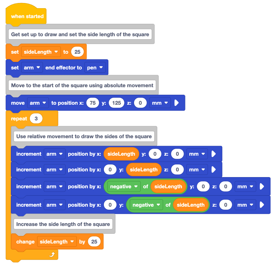
Activity: Follow the procedure you learned in Lesson 2 to read and document the code in the project above.
- Document the project above in your engineering notebook.
- Predict what you think the 6-Axis Arm will do when the project is run. Document your prediction in your engineering notebook.
- Read each block in the project, and visualize the behavior the 6-Axis Arm would perform when executing the block. Record this behavior in your engineering notebook.
- Sketch the path the 6-Axis Arm would take when the project is run. What shape(s) are made?
- Predict the value that the sideLength variable will be at the end of the project. Document this value in your engineering notebook.
- Check in with your teacher when you are finished. You will watch the project run as a class. Then you will discuss your prediction and documentation.
Check Your Understanding
Before moving to the next Lesson, ensure that you understand the concepts in this Lesson by answering the questions in the document below in your engineering notebook.
Check Your Understanding questions > (Google Doc / .docx / .pdf)
Select Next > to complete the Putting It All Together activity.