
Previously you moved the 6-Axis Arm to specific coordinates to draw various shapes. In this Lesson, you will learn another way to move the 6-Axis Arm to draw a square. You will be introduced to the concepts of absolute and relative movement, so that you can combine the two kinds of motion to code the 6-Axis Arm.
In this Lesson you will learn:
- The difference between absolute and relative movement.
- When to apply absolute or relative movement in a project to move the 6-Axis Arm as intended.
- How to use Increment position blocks in a project to code relative movements.
By the end of this Lesson you will code the 6-Axis Arm to draw squares, using a combination of absolute and relative movements.
Drawing a Square with Absolute Movement
In the previous Unit, you drew a square by finding the coordinates of each point, and moving the 6-Axis Arm to those specific locations. Let's review this process, so we can pay attention to the kind of movement the 6-Axis Arm is using.
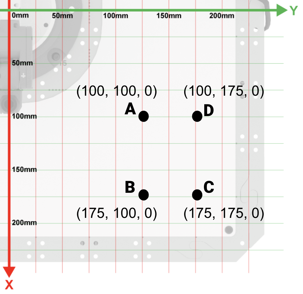
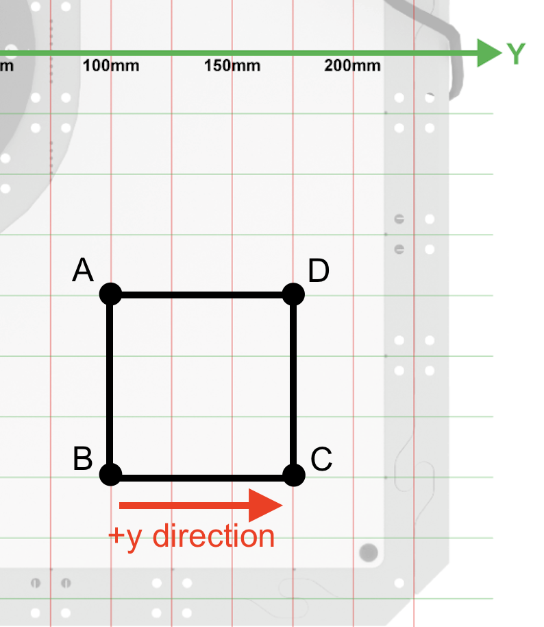
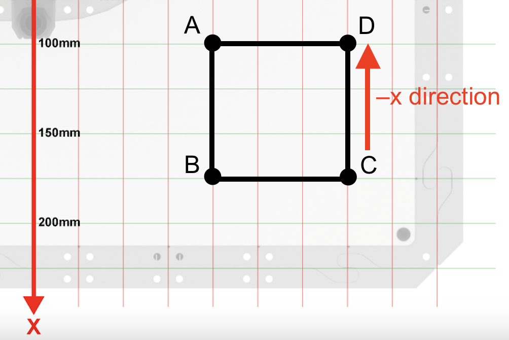
Document the coordinates of square ABCD.
In your engineering notebook, record the known information about the square.
- Each side length is 75mm
- Point A is (100, 100, 0)
- Point B is (175, 100, 0)
- Point C is (175, 175, 0)
- Point D is (100, 175, 0)
Open a New Blocks Project by following the steps in this video.
Select the File option in the Toolbar to open the File menu, then select New Blocks Project. A pop up window appears with the option for EXP Brain or 6-Axis Arm. Select 6-Axis Arm. The new project is then opened.
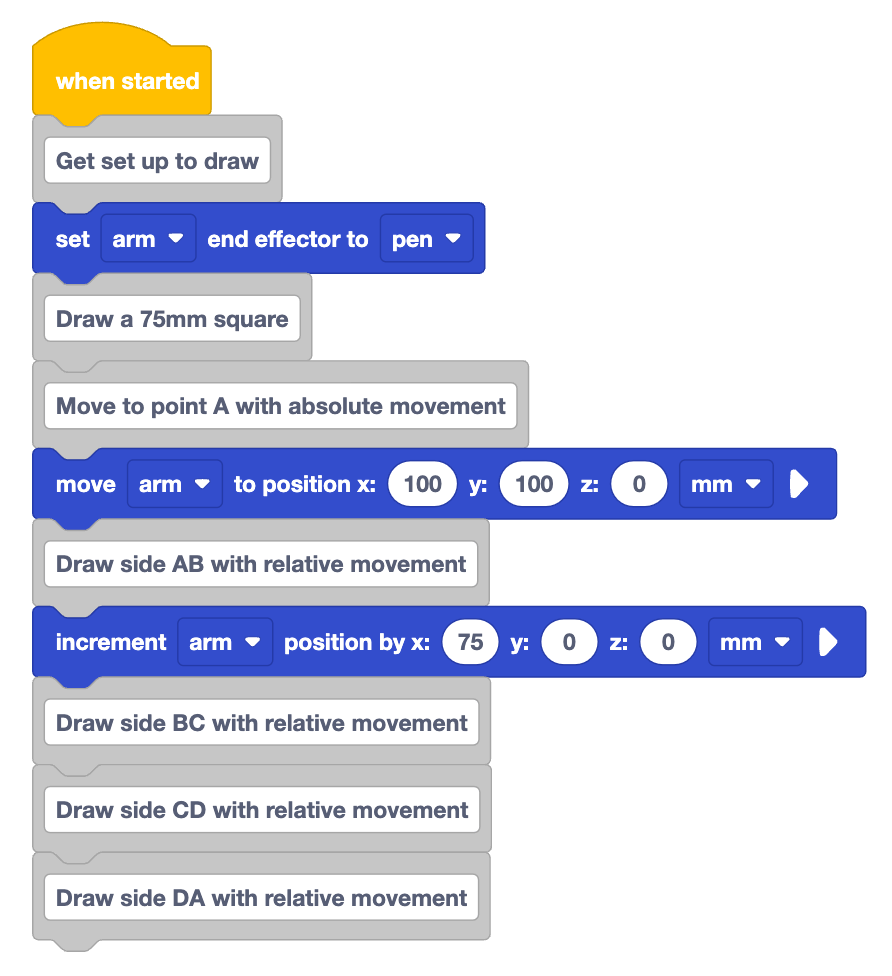
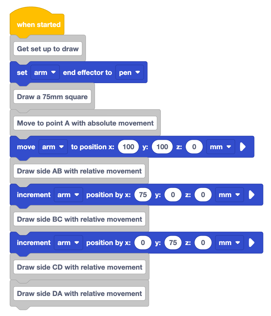
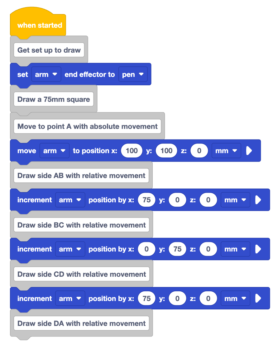
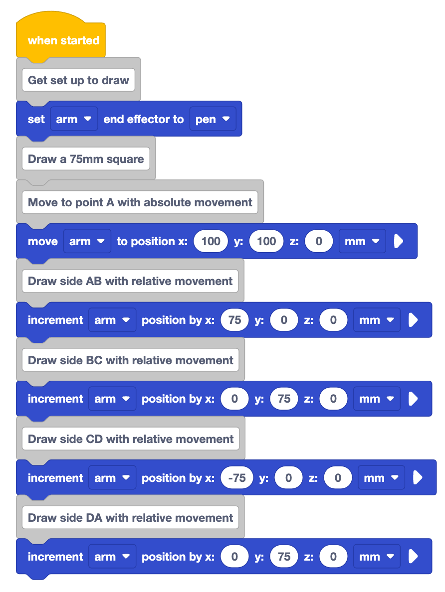
Recreate the project shown here in VEXcode.
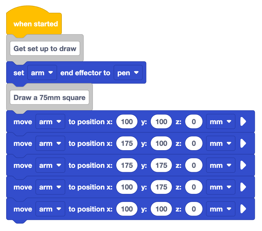
Look at the blocks in the project. What do you think the 6-Axis Arm will do when this project is run?
Record your prediction in your engineering notebook. Describe how the 6-Axis Arm will move in words, and sketch what you think will be drawn on the Whiteboard.

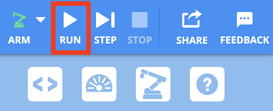
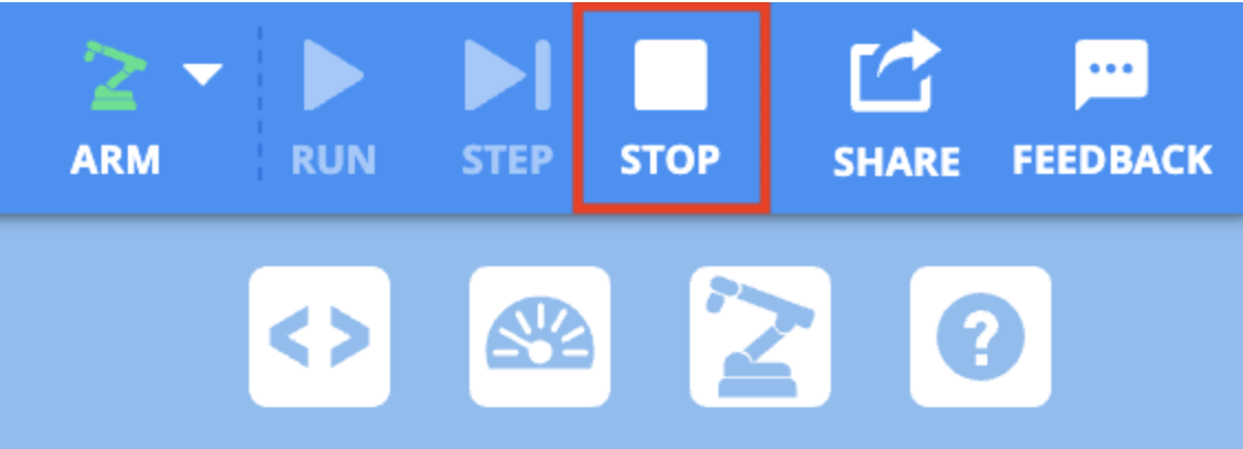
Be sure the 6-Axis Arm is connected to VEXcode. Run the project and observe the behavior of the 6-Axis Arm.
Stop the project when the 6-Axis Arm has finished moving.
Did the 6-Axis Arm draw what you predicted it would? Why or why not?
In this project, the 6-Axis Arm uses absolute movement to draw the square. That means that the 6-Axis Arm moves to specific coordinates in order to draw each side of the square. It will reach those same coordinates no matter where the 6-Axis Arm was positioned before. This can be useful at times, but requires us to have exact coordinates for every point in the shape we are making. There is another way to use the information about side lengths in a project to draw a square.
Drawing a Square with Relative Movement
Understanding the lengths of the square's sides helps us figure out how much the 6-Axis Arm needs to move relative to its current position to draw each side accurately. Instead of pinpointing all four corners of the square, we can simply move the arm relative to the starting point to complete the shape.
What is relative movement?
Relative movement moves the 6-Axis Arm to a new position based on its current location. Given a starting point, and the lengths of the sides of the square, we can move the 6-Axis Arm along the x and y-axes relative to the starting position. Let's break this down with our 75mm square.
We will start with an absolute movement to get to the starting coordinate. From there, each of the sides can be drawn with relative movement. 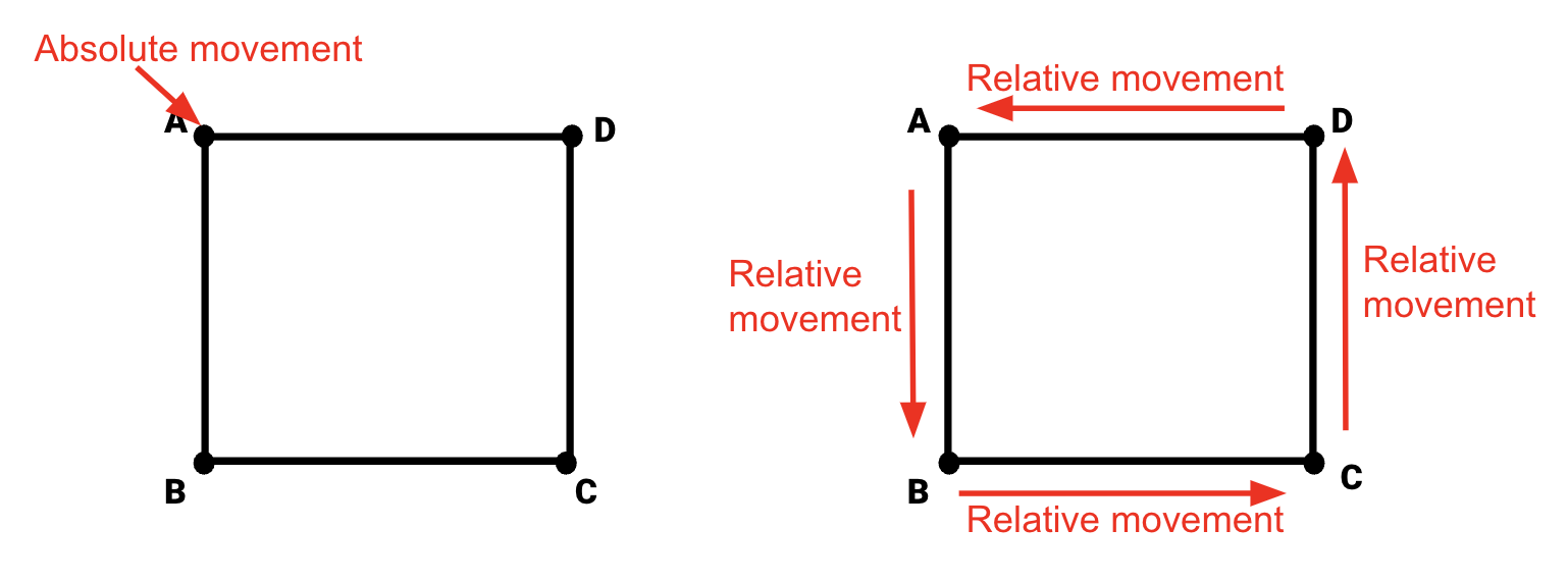
Let's edit our project to see this in action.
Remove the Move to position blocks used to draw the square.
The video here shows the bottom five blocks of the project run earlier being deleted. The blocks that remain are the two comments and the Set end effector block.
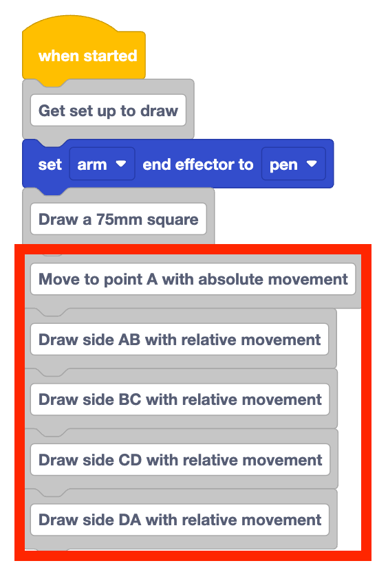
Add five Comment blocks to the project, to describe the movement of the 6-Axis Arm to draw each side of the square. Type the following comments into the project:
- Move to point A with absolute movement
- Draw side AB with relative movement
- Draw side BC with relative movement
- Draw side CD with relative movement
- Draw side DA with relative movement
Adding comments like this is helpful to stay organized, and show the steps needed in sequence to complete the task at hand.
Drawing Side AB with Relative Movement
Add a Move to position block beneath the comment "Move to point A with absolute movement". Input the starting coordinate (point A) in the parameters.
- Point A (100, 100, 0)
This project begins the same as the previous one, as it begins with an absolute movement.

To draw side AB with relative movement we will use a Increment position block. 
The Increment position block moves the 6-Axis Arm for a particular distance along the x, y, z-axes. This is the block we will use to move the 6-Axis Arm with relative movement. The Increment position block moves the 6-Axis Arm for a distance relative to its current location.
Add an Increment position block beneath the comment "Draw side AB with relative movement".
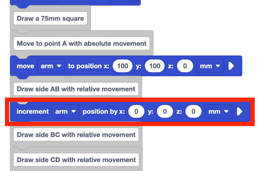
Notice that the Increment position block has parameters for the x, y, and z-axes. This is related to how far the 6-Axis Arm will move along each axis, or the relative movement of the 6-Axis Arm on each axis. These parameters are not a coordinate value, like they were in the Move to position block, when the 6-Axis Arm used absolute movement.
To determine the parameter(s) needed to draw a side of the square two pieces of information are needed:
- the distance to move the 6-Axis Arm relative to the current position
- the axis or axes the 6-Axis Arm will move along
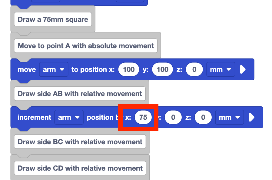
To draw side AB of the square, the distance the 6-Axis Arm will move relative to the current position is the side length, or 75mm. To move from point A to point B, the 6-Axis Arm will move along the x-axis in the positive direction. It will not move along the y or z-axes.

Set the x parameter to 75 in the Increment position block. The y and z parameters remain 0.
This will move the 6-Axis Arm for 75mm along the x-axis only, in the positive direction.
Look at the project as it is right now. What do you think this will cause the 6-Axis Arm to do when it is run?
Record your prediction in your engineering notebook. Draw what you think the 6-Axis Arm will draw.
Be sure the 6-Axis Arm is connected to VEXcode. Run the project and observe the behavior of the 6-Axis Arm.

Stop the project when the 6-Axis Arm has stopped moving.
Did the 6-Axis Arm move as you predicted? Why or why not?

Drawing Side BC with Relative Movement
We can apply what we learned to draw the first side of the square, to draw side BC.
Add an Increment position block below the comment "Draw side BC with relative movement".
Determine the parameters of the Increment position block.
To draw side BC, the 6-Axis Arm needs to move for 75mm. Looking at the direction of movement relative to the current position, we see that the 6-Axis Arm needs to move along the y-axis. The 6-Axis Arm should not move along the x or z-axes.
Set the y parameter of the Increment position block to 75.
This will move the 6-Axis Arm for 75mm along the y-axis. Since the parameters for the x and z-axes are 0, the 6-Axis Arm will not move on the x or z-axes.
Predict how you think the 6-Axis Arm will move when the project is run. Record your prediction in your engineering notebook.
Sketch what you think the 6-Axis Arm will draw.
Run the project and observe the behavior of the 6-Axis Arm.
Stop the project when the 6-Axis Arm has finished moving.
Did the 6-Axis Arm draw what you predicted it would? Why or why not?

Drawing Side CD with Relative Movement
Now that we've drawn the first two sides of the square, we can continue to build onto our project to draw side CD.
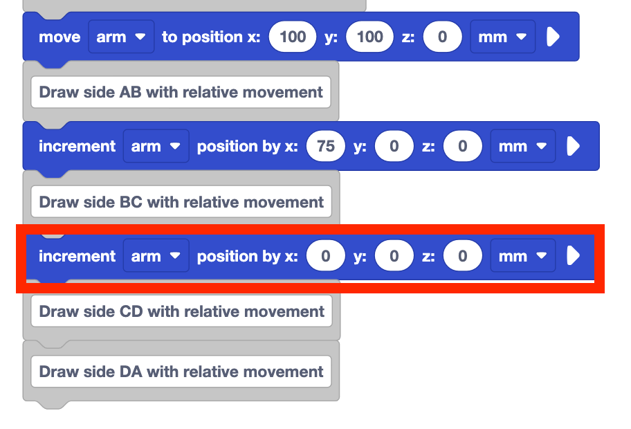
Add an Increment position block below the comment "Draw side CD with relative movement".
Determine the parameters for the Increment position block.
To draw side CD, the side length is still 75mm. Looking at the direction of that movement relative to the current position of the 6-Axis Arm, we see that the movement is again along the x-axis.
The 6-Axis Arm should not move on the y or z-axes on this side of the square.
Set the x parameter of the Increment position block to 75.

Predict how you think the 6-Axis Arm will move when the project is run. Record your prediction in your engineering notebook, and be sure to include a sketch of what you think will be drawn.
Run the project and observe the behavior of the 6-Axis Arm.
Did it draw what you predicted it would? Why or why not?

The 6-Axis Arm did not draw side CD as intended.
Let's look at why that happened. The side length did not change, so the length of the line drawn is correct. However, the direction of that movement is not.
We can account for moving in a positive or negative direction by entering the parameter in the Increment position block as a positive or negative number.
For sides AB and BC, the 6-Axis Arm was moving in the positive direction along the x and y-axes, so we used a positive number. But to draw side CD, the 6-Axis Arm needs to move in the negative direction, so we will need to use a negative value in the parameter.
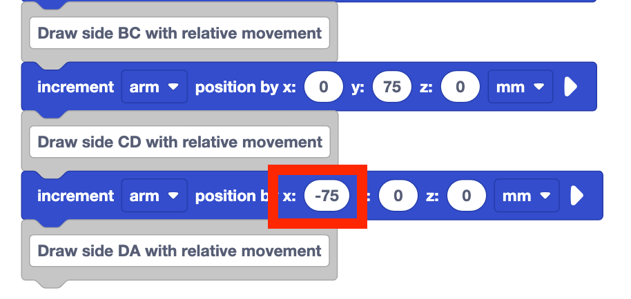
Set the x parameter of the Increment position block to –75.
This will move the 6-Axis Arm for 75mm in the negative direction along the x-axis. The y and z-axis values do not need to change, as the 6-Axis Arm is still not moving along those axes to draw side CD.
Run the project again, and observe the behavior of the 6-Axis Arm.
Is side CD drawn as intended? Why or why not?
Drawing Side DA with Relative Movement
Now that we have three sides of the square drawn, we can apply what we have learned to draw the final side.
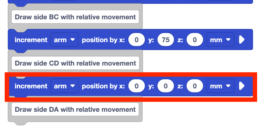
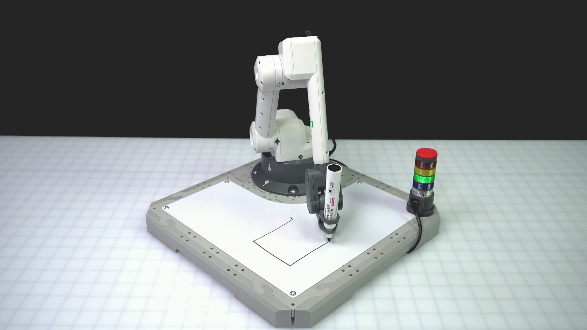
Add an Increment position block below the comment "Draw side DA with relative movement".
Determine the parameters for the Increment position block.
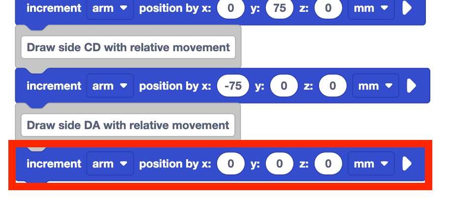
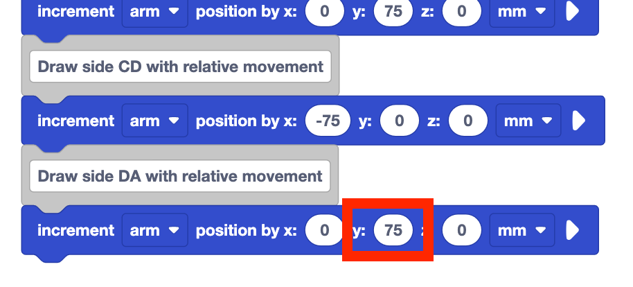
To draw side DA, the 6-Axis Arm is again moving for 75mm. Looking at the direction of that movement based on the current position, the 6-Axis Arm will need to move along the y-axis again. It does not need to move along the x or z-axes to draw side DA.

Set the y-parameter of the Increment position block to 75. The x and z-parameters should remain 0.
Predict how the 6-Axis Arm will move and what it will draw when the project is run. Record your prediction in your engineering notebook.
Run the project and observe the behavior of the 6-Axis Arm.
Does it move as you predicted? Does it draw the final side of the square as intended? Why or why not?

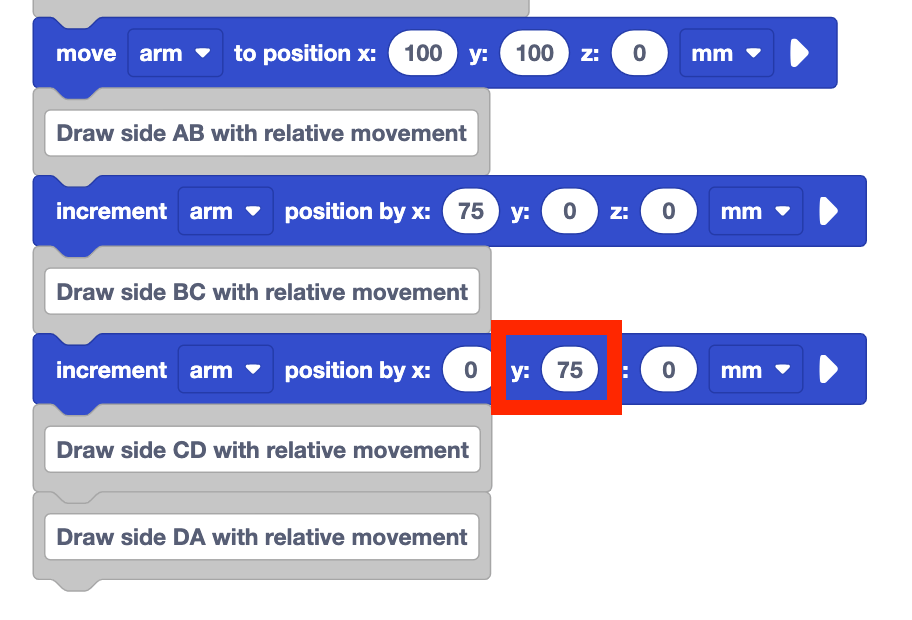
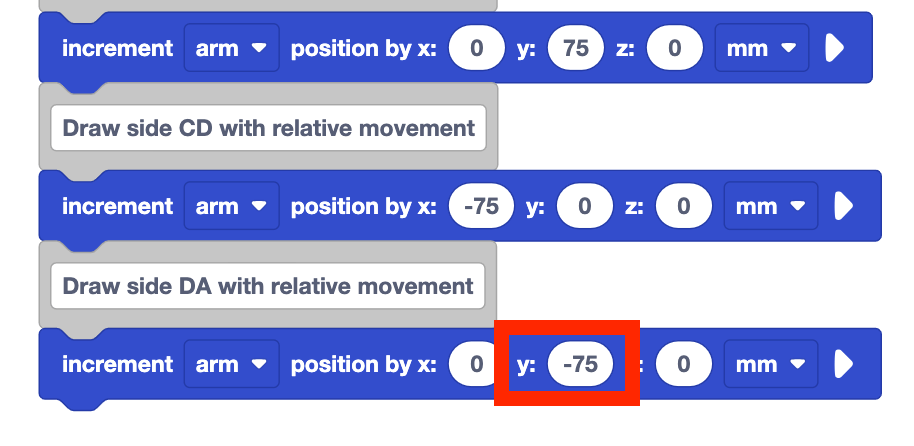
To draw side DA as intended, the 6-Axis Arm needed to move in the negative direction along the y-axis. However, we set the y-parameter to 75mm, indicating that the 6-Axis Arm should move in the positive direction along the y-axis.

Set the y parameter of the final Increment position block to –75. The x and z parameters should remain 0, as the 6-Axis Arm does not need to move on these axes to draw side DA as intended.
The 6-Axis Arm should now move along the y-axis in the negative direction to complete the square.
Run the project and observe the movement of the 6-Axis Arm.
Does it draw the square as intended? Why or why not?
Be sure to rename and save your project.

Why Use Relative Movement?
While the motion of the 6-Axis Arm is the same to draw a 75mm square with both absolute and relative movement, there is additional flexibility and ease when we use relative movement. For instance, if you wanted to draw a 75mm square in a different location, what would you do? Using absolute movement, you would find the new coordinates of all four points and code the 6-Axis Arm to connect them. Using relative movement however, you only need to know the starting coordinate, and the rest remains the same.
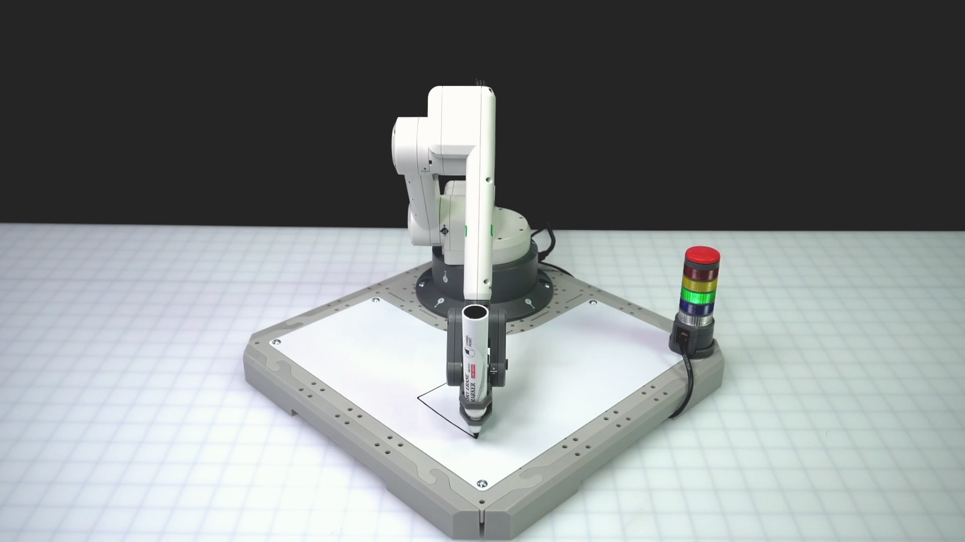
Absolute movement will always take you to the same coordinate, no matter the starting location. This is useful when you need to move the 6-Axis Arm to a specific location to start a project, or to ensure you can reach that location regardless of the previous coordinates. The video below shows a marker starting at three different locations on the whiteboard attachment. All markers move to the location (75, 75, 0) because they are moving with absolute movement.
Relative movement will move to a new location based on the current position. This is useful when you need to move the 6-Axis Arm in relation to a known location, like you did when drawing a square or to move in a specific pattern. The video below shows a marker starting at the same three locations as above on the whiteboard attachment. All markers move diagonal at the same time because their x value was increased by 75 and their y value was increased by 75 at the same time. The end locations of the markers are all different and directly relate to their starting positions with that increase in x and y values.
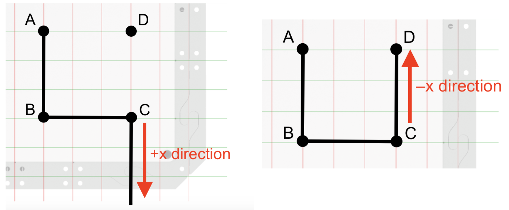
Both projects in this Lesson used the same information, but the way that it was used in the code was different. Let's look at our projects in more detail. The image on the left is from our absolute movement project. The side length of 75mm corresponds to the change in the x-coordinate needed to move from point A to point B.
The image on the right is from our relative movement project. Here the side length of 75mm corresponds to how far the 6-Axis Arm moves along the x-axis. 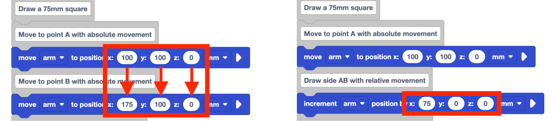
Using relative movement can give you added flexibility in your project, so make adapting and adjusting your code for various purposes simpler.
Activity
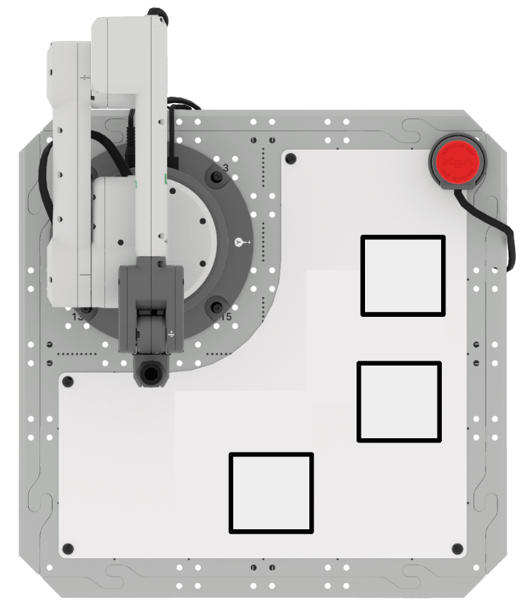
Now that you have coded the 6-Axis Axis Arm to move using both absolute and relative movement, it is time to practice these skills. In this Activity, you will edit your project to code the 6-Axis Arm to draw three squares on the Whiteboard. 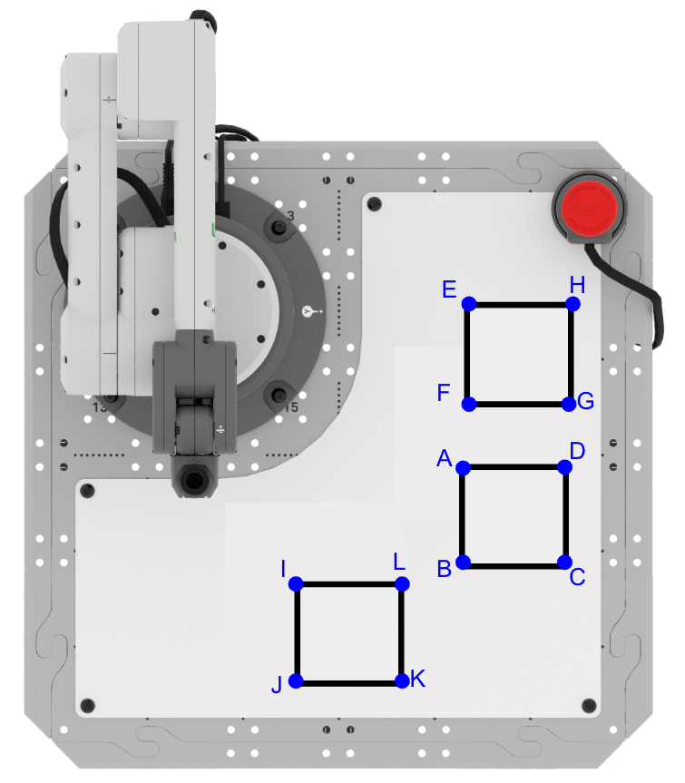
Setup: Record the following information in your engineering notebook.
- The starting coordinates for each square is as follows:
- Square ABCD (100, 150, 0)
- Square EFGH (-5, 153, 0)
- Square IJKL (155, 57, 0)
- All side lengths of the three squares are 50mm.
- The squares cannot touch one another.
Activity: Build onto your project from this Lesson to code the 6-Axis Arm to draw two additional squares.
- Record a plan for your project in your engineering notebook. Be sure your group agrees on which square to draw first, second and third, as well as what kinds of movements you will use to complete the drawings.
- Build onto your project from this Lesson to follow your plan in your engineering notebook.
- Run your project to test it. Ensure your 6-Axis Arm is connected to VEXcode. Does your project draw all three squares as intended? Why or why not?
- Continue to iterate on your project until you have successfully drawn all three squares. Name and save your project when you have finished.
Check Your Understanding
Before beginning the next Lesson, ensure that you understand the concepts in this Lesson by answering the questions in the document below in your engineering notebook.
Check Your Understanding questions > (Google Doc / .docx / .pdf)
Select Next > to move on to Lesson 2.