
The Grabber's Linkages
![]() Teacher Toolbox
-
The Purpose of this Section
Teacher Toolbox
-
The Purpose of this Section
The goal of the Play section is to allow students to test the build and help them explore converting motion with linkages. Allow the students to test how the Grabber moves. The Motivate Discussion section provides questions to get students thinking about how scissor linkages change the direction of a force and how the Grabber's build could be improved. The second page of the Play section will introduce scissor linkages used within professional scissor lifts to provide another familiar context for analysis.
When working in groups, the following student roles can be assigned:
-
Build Expert: Responsible for understanding the Grabber's structure and demonstrating the build's operation at different points during the activity.
-
Recorder: Responsible for documenting feedback from the entire team within the engineering notebook.
If groups are larger than two, more than one student can share the responsibilities of the same role.
A team-based engineering notebook rubric is available by clicking here (Google / .docx / .pdf) and a collaboration rubric is available by clicking here (Google / .docx / .pdf). For a rubric to score individual engineering notebooks, click here (Google / .docx / .pdf).
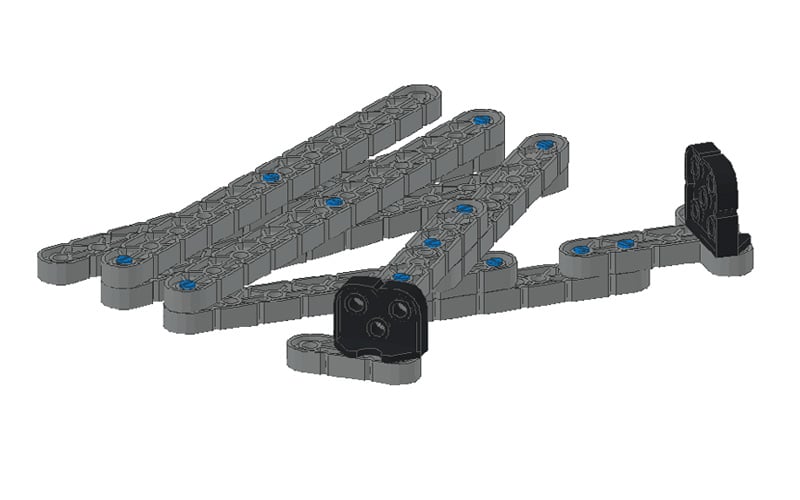
Step 1: Examine the Grabber

In Step 2 of the Grabber build, you created a linkage by attaching two beams together at the center using a pin. This created a scissor linkage. That should be easy to remember when you think of how the sides of scissors move around a center point.
- Build Expert: hold the ends of the bottom two beams in each of your hands. Close and open the Grabber by moving your hands apart and back together again, similar to using a single pair of scissors but with two hands.
- Recorder: sketch and explain in your engineering notebook how the Build Expert's movements compare to the movements of the Grabber. Compare the direction of each beam's movements and identify a pattern.
Hint: Look at how the pins affect the beams' movements.
![]() Teacher Toolbox
-
Answers
Teacher Toolbox
-
Answers
The pattern to notice is that as the Build Expert moves the ends of the Grabber closer and farther apart, the pins act as pivot points and the beams move inward and outward, respectively.
Step 2: Consider Extending the Grabber
The Grabber has three scissor linkages. Adding more scissor linkages would allow the grabber to lift or extend further.
- Build Expert: place the Grabber down so that it is halfway opened. Consider how much longer the Grabber would be if two more scissor linkages were added to the build. You can use the length of the two bottom beams to estimate.
- Recorder: sketch what the extended Grabber build would look like. Explain why adding two more scissor linkages might not be a good design plan. What could change about how the Grabber works if two more linkages are added to the build?
![]() Teacher Toolbox
-
Answers
Teacher Toolbox
-
Answers
Adding two more scissor linkages would change how much force is needed to control the Grabber and would decrease the stability of the build. The longer Grabber would require more force to push out or pull in. The added weight would also put more stress on the beams and especially the pins and therefore, decrease its stability.
![]() Motivate Discussion
Motivate Discussion
Q: When the user pushes the ends of the Grabber's handles together, does the grabbing end move closer together (pinch) or move farther apart (open)?
A: The grabbing end moves closer together (pinches or grabs) when the user moves the handles closer together.
Q: Does the force created by pushing or pulling the Grabber's handles always move in the same direction or does it change directions? If it changes directions, where does the force change directions?
A: The force created by pushing or pulling the Grabber's handles changes directions several times each at pivot point or pinned connection in the build.
Q: As further linkages are added, how can you improve the build to make it more rigid and stable?
A: One possible solution is to use thicker beams to provide more stability (a 2x4 Beam instead of a 1x4 Beam would be an example). Another possible solution is to use longer pins (a 1x2 or a 2x2 instead of a 1x1 Connector Pin).
![]() Extend Your Learning
Extend Your Learning
To expand this activity, explain to the students that a simple lever is an example of a two-bar linkage like a scissor linkage. The ground is considered one link connected at a joint, or fulcrum, to the lever. In the scissor linkage, there is not a joint created by a fulcrum but a pivot point created by a pin.
Have the students explore more complex linkages and record their designs/details in their engineering notebooks.


Some examples of more complex linkages are:
- Binary Link
- Ternary Link
- Quaternary Link
- Pentanary Link