
In the previous Lesson, you learned how to use the Pen Holder Tool and code the 6-Axis Arm to draw a line on the Whiteboard. In this Lesson, you will continue to use the Pen as you learn to control the path of the 6-Axis Arm in order to move around obstacles. You will learn:
- how to identify a waypoint to move the 6-Axis Arm around an obstacle.
- how to code the 6-Axis Arm to travel in a controlled path using a waypoint.
By the end of this Lesson, you will determine the waypoint needed and code the 6-Axis Arm to move around an obstacle.
Watch the animation below to see the 6-Axis Arm use waypoints to draw lines. First, the 6-Axis Arm draws a diagonal line connecting two waypoints, and next, it connects three waypoints in a right angle to avoid an cube placed on the Tile.
Why Control the Path of the 6-Axis Arm?
Imagine multiple robotic arms working together to assemble a product on an assembly line. The robotic arms must navigate quickly around each other with a high degree of accuracy. Each arm must travel its own complicated path in order for the operation to be successful. This is accomplished by controlling the path of each arm by coding it to travel along a series of waypoints. This prevents the arms from colliding with each other or with the product they are assembling.

Previously, you coded the 6-Axis Arm to travel from one point to another in a straight line. However, there were no obstacles present to prevent the 6-Axis Arm from going directly from one location to another. In this Lesson, there will be an obstacle present, so you will need identify a waypoint that will allow you to code the 6-Axis Arm to navigate around the obstacle.
Coding the 6-Axis Arm to Follow a Controlled Path
The 6-Axis Arm must move from point A to point B, but there is an obstacle directly between the two points.

Because of this, you must find a waypoint to allow you to code the 6-Axis Arm to move around the obstacle in order for the 6-Axis Arm to reach its destination. A waypoint is an intermediate point between two locations on a line of travel. In the image below, point C is a waypoint. Instead of traveling directly from point A to point B, the 6-Axis Arm can travel from point A, to point C, and then to point B, in order to avoid colliding with the obstacle.

For Your Information
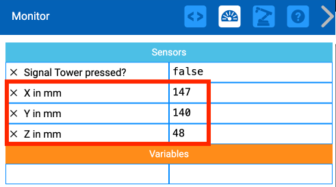
The Monitor in VEXcode EXP can be helpful in locating specific coordinates on the Whiteboard. The x, y, z coordinate values will update in real time on the Monitor as the 6-Axis Arm is manually moved, allowing you to easily find specific points (as in Step 1, below).
Finding a Waypoint
Setup your Whiteboard as shown here. Be sure to use a whiteboard marker to write on the Whiteboard.
Point A is located at approximately (150, 50, 0).
Point B is located at approximately (50, 150, 0).
Draw a line from point B to the bottom of the Whiteboard, parallel to the x-axis.

Next, draw a line from point A to the edge of the Whiteboard, parallel to the y-axis.

The intersection of these two lines is your waypoint. Mark the intersection and label it point C.
This point will allow clearance for the 6-Axis Arm to move from point A to point B without hitting the obstacle.

Next you will need to determine the coordinates of point C. You will find the x-coordinate first.
Measure the distance between points B and C and record it in your engineering notebook.
Note: These measurements are approximate, yours may vary slightly. Be sure to use your measurements in your calculations.

We can use the known x-coordinate of point B, and the measured distance the 6-Axis Arm needs to move along the x-axis, to find the x-coordinate of point C.
In this formula, the 'delta' represents a change in values. The distance you measured is the change in the x-values between points B and C.

Input your values to calculate the x-coordinate of point C in your engineering notebook.
In this example, the x-coordinate of C is 163mm.

Follow the same process to find the y-coordinate of point C. First, measure the distance between point A and point C and record it in your engineering notebook. This is the distance along the y-axis that your 6-Axis Arm needs to move.

We can use the known y-coordinate of point A, and the measured distance the 6-Axis Arm needs to move along the y-axis, to find the y-coordinate of point C.
In this formula, the 'delta' represents a change in values. The distance you measured is the change in the y-values between points A and C.

Input your values to calculate the y-coordinate of point C in your engineering notebook.
In this example, the y-coordinate of C is 165mm.

Coding the 6-Axis Arm to Travel Around the Obstacle
Now that you have determined the coordinates for point C, it is time to create a VEXcode EXP project for the 6-Axis Arm to travel from point A to point B, via the waypoint, point C.
Open your project from Lesson 1 in VEXcode EXP. You will modify this project by adding a Move to position block in order to code the 6-Axis Arm to travel from point A to point C, then to point B.

Drag an additional Move to position block into the Workspace. Input the x and y-coordinates you calculated earlier into the parameters of the block.

Consider the path the 6-Axis Arm must take. First the Pen moves to point A, and then it moves to point C. So, the new Move to position block will need to be inserted into the project between the two Move to position blocks.

Rename your project, and then save it to your device.
In your engineering notebook, record the path you think the 6-Axis Arm will take when the project is run. You can do this with a drawing, or in words.

Be sure the 6-Axis Arm is connected to VEXcode. Run your project.
The 6-Axis Arm will avoid colliding with the obstacle by going around it. It will move from point A, to the waypoint C, and end at point B.
View this video to see an example of the 6-Axis Arm moving in this path.
Activity
Now that you have learned to find a waypoint and code the robot to travel using it, you will practice this skill. In this activity, you will create a project for the 6-Axis Arm to move in a controlled path from one new point to another new point, without colliding with the obstacle.

- Setup: Draw the start and end locations (A and B) on the Whiteboard as shown above. You can use the coordinates shown in the image to help you set up the activity.
- Point A is located at approximately (175, 0, 0)
- Point B is located at approximately (-25, 150, 0)
- Set an obstacle between points A and B. In the image above the obstacle (a Cube) is located at approximately (100, 125, 0)
- Activity: Create a VEXcode EXP project for the 6-Axis Arm to travel from point A to point B without colliding with the obstacle. Use a waypoint to do so.
- Run your project to test it. Does it successfully move from point A to point B without colliding with the obstacle? If not, modify your project and test it again.
- Record the process you used to find the waypoint in your engineering notebook, and include details about how you used this information in your project.
Check Your Understanding
Before moving to the next Lesson, ensure that you understand the concepts in this Lesson by answering the questions in the document below in your engineering notebook.
Check Your Understanding questions > (Google Doc / .docx / .pdf)
Select Next > to complete the Mid-Unit Reflection.