
In this Lesson, you will learn about another important safety measure that prevents accidents and ensures worker safety, the emergency stop.
You will learn:
- What an emergency stop is, and what it is used for.
- The difference between controlled and uncontrolled stops.
- Other safety mechanisms and standards in industrial robotics.
- How the controlled stop on the CTE Workcell functions.
At the end of this Lesson, you will review what you learned as you answer questions in your engineering notebook.
Emergency Stops
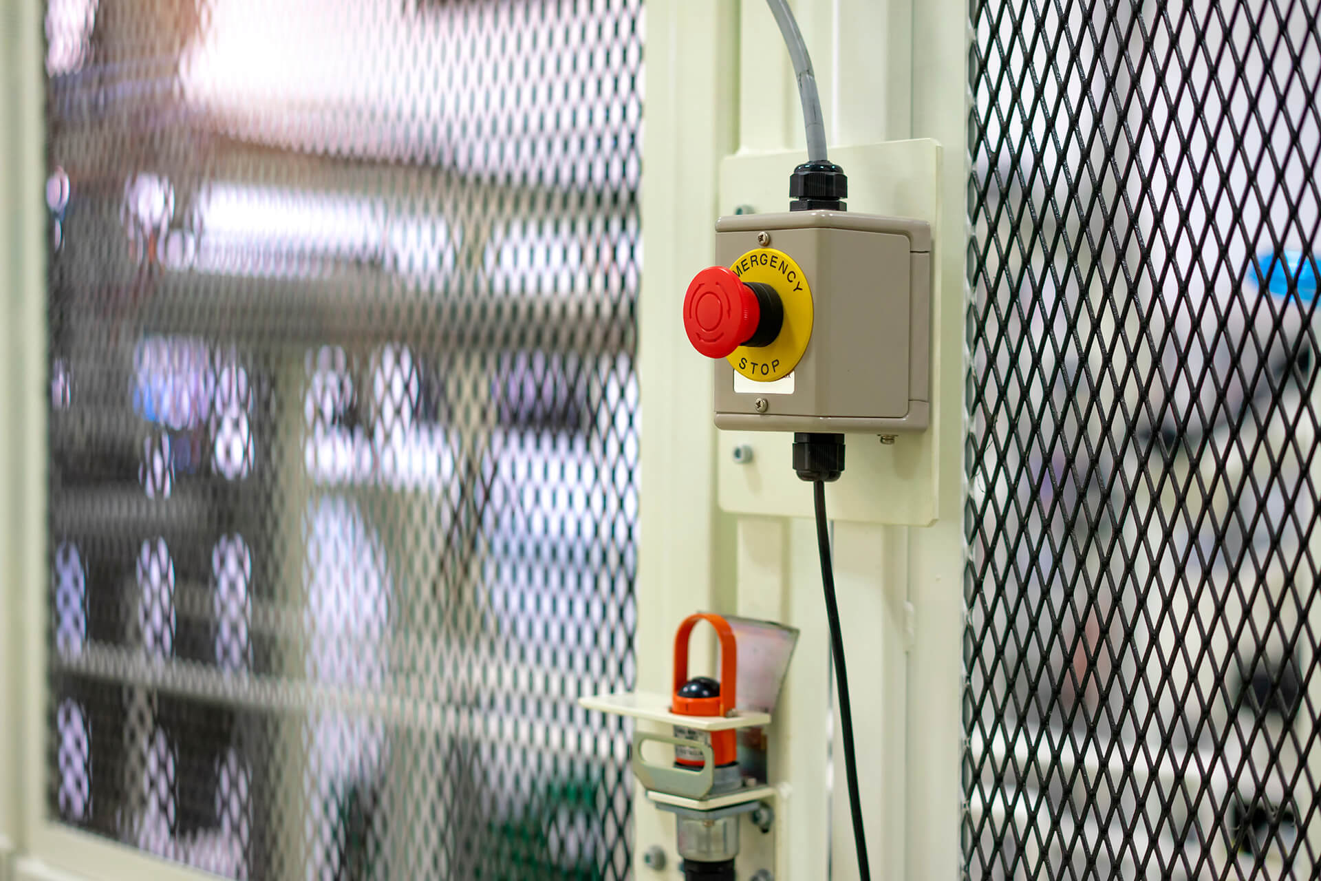
An emergency stop, also known as an e-stop, is a vital safety mechanism designed to keep workers and equipment safe from harm in the event of a hazardous situation. E-stops are standard throughout industrial automation, and are designed to swiftly halt robotic operations in emergencies, preventing injuries to workers and safeguarding equipment. An e-stop is triggered by a single action, such as a push button. Once an e-stop has been initiated, an operator must act intentionally in order to safely restart operations.
In industrial robotics, emergency stops can be initiated in a variety of circumstances. For example, a motor failure or programming error could pose a risk to equipment or personnel. When the error is detected, an e-stop could be initiated by a worker, telling the workcell to cease operations. Other instances where e-stops could be activated include unforeseen dangers, such as:
- fires.
- a worker stepping into the path of a robotic arm.
- an obstruction falling into the range of a robotic arm making a collision likely.
Triggering an e-stop can prevent harm to workers and help to avoid expensive damages.
Controlled Stops vs. Uncontrolled Stops
There are two categories of emergency stops: controlled, and uncontrolled. Whether to use a controlled or uncontrolled stop depends on the situation. A controlled stop gradually ramps down but does not fully remove the power to the machines. For example, if workers were positioned underneath a heavy car chassis on an assembly line, and an emergency stop were triggered due to an obstruction of a robotic arm, a controlled stop would be used. This would gradually slow down any motion, allowing the machinery to come to a smooth stop, giving the workers time to step out of the way.
An uncontrolled stop immediately removes all power to the machines. In the car chassis example, the removal of all power could cause the chassis to fall on the workers below. However, in an event like an electrical fire, an uncontrolled stop would be used, as it would cut all power to the machinery immediately.
Standards for Emergency Stops in Industrial Robotics
Industry wide standards and laws govern the use of e-stops in industrial robotics, helping to ensure a high standard of worker safety across industry. Some of these standards bodies include:
- Robotic Industry Association (RIA): The association that sets safety standards for industrial robots.
- American National Standards Institute (ANSI): An institute that maintains standards for workplace safety in the United States.
- International Organization for Standardization (ISO): An organization that maintains the international standards for workplace safety.
- Occupational Safety and Health Administration (OSHA): The federal administration that sets and enforces workplace safety regulations.
Types of standardization include the type of mechanism used to trigger an e stop, the color of the mechanism, and the positioning of the mechanism. For example, e-stops should be colored red and yellow, for high visibility. They should require only a single action in order to initiate them, and should be positioned outside of a robotic arm's reach, so workers do not need to cross into harm's way to activate them. They also should be placed in a location that is easily accessible to operators. These are just a few of the standards in place to keep workers safe when using e-stops.

Other Safety Mechanisms
Many other devices are used to help ensure the safety of operators of industrial robots. Safety mechanisms are often used in conjunction with one another. Real world industrial settings use a variety of safety devices, mechanisms, and precautions in order to ensure worker safety, including:
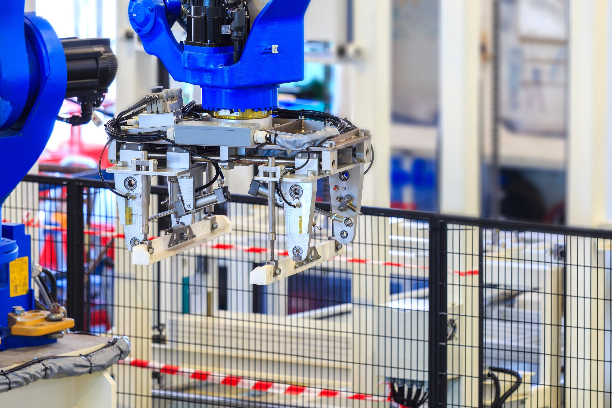
- Safety Barriers and Guards: Physical barriers that separate robots from human workers to prevent accidental contact. These include fences, cages, and other structures designed to restrict access to dangerous areas.
- Presence Sensing Devices: Sensors that detect the presence of humans or objects within a specified area. These can stop robot operation if an intrusion is detected.
- Sensor Arms: Robotic arms equipped with sensors to detect contact with humans or objects. These sensors can trigger a shutdown or slow down the robot to prevent injury or damage.
- Pressure Mat: Mats placed on the floor around the robot that detect pressure or weight. If a person steps on the mat, the robot will stop operating to prevent accidents.
- Alarms: Audible and visual warning systems that alert workers to the presence of an active robot or an unsafe condition. These alarms can be triggered by various safety systems or manually by operators.
- Light Curtains: Arrays of light beams that create an invisible barrier around hazardous areas. If any beam is interrupted, the robot is stopped immediately to ensure the safety of personnel.
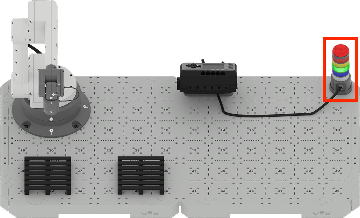
The Controlled Stop on the CTE Workcell
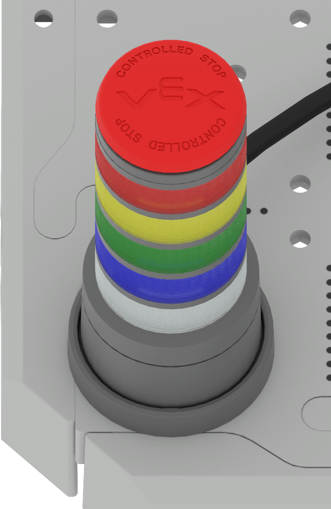
On the CTE Workcell, a button on the top of the Signal Tower can trigger a controlled stop when pressed.
You will notice that the button says "Controlled Stop" on the surface. When coded to serve as an controlled stop, the button can be pressed if any component of the Workcell is moving in a way that is damaging to itself, or the user.
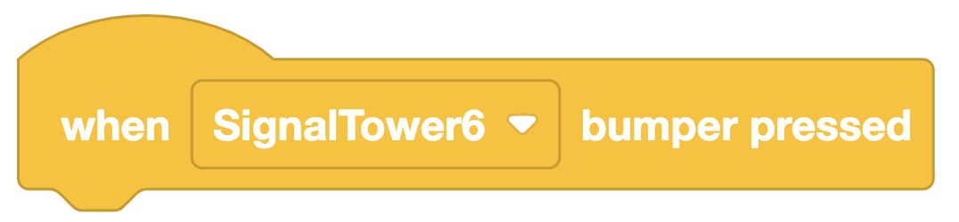
The When signal tower bumper pressed? block is used to code the controlled stop functionality.
There is a stack of blocks in the Brain CTE 6-Axis Arm Template project that enables controlled stop functionality. You will learn more about coding the Signal Tower in the next Lesson.
You will notice that the Signal Tower on your build is located out of the path of the 6-Axis Arm, so that it can be easily pressed in a safe way if needed.
Check Your Understanding
Before you move on to the next Lesson, ensure that you understand the concepts covered in this Lesson by answering the questions in the document below in your engineering notebook.
Check Your Understanding questions > (Google Doc / .docx / .pdf)
Select Next > to move on to the next Lesson.