Math Support
When teaching Labs 4 and 5, additional mathematics concepts and calculations are involved. This page offers teachers relevant background resources to support the math that students are exploring in these Labs.
Mathematics of Driving
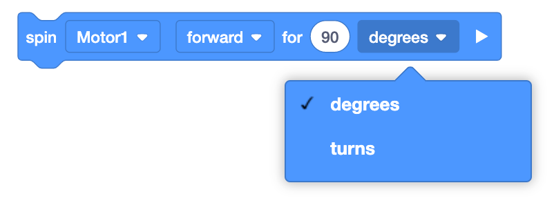
To complete the parade in Lab 4, students will drive their Code Base float along a straight parade route distance. Instead of using drivetrain blocks that move both of the wheels at the same time, students will use the [Spin for] blocks in VEXcode GO, as shown here, to spin the motors connected to the wheels and move the robot forward. [Spin for] blocks accept 'turns' or 'degrees' as parameters. In Lab 4, students will calculate the number of turns to input into this project to drive their robot the distance of the parade route.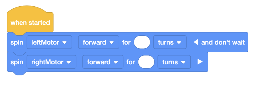
Watch the video below to learn about how to calculate the number of wheel turns needed to drive your robot straight for a set distance.
Helpful References:
Terminology and Values for the Gray Wheels:
| Term | Definition | Visual | Formula | Value |
|---|---|---|---|---|
| Diameter | Measurement of a straight line across the center of a circle | 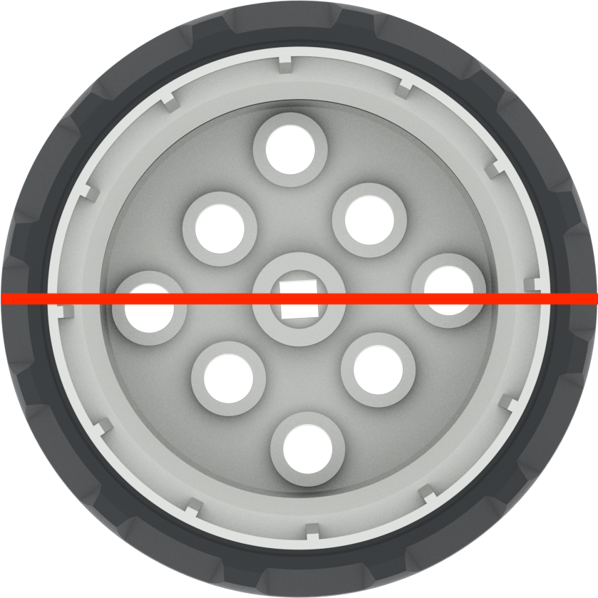 |
d = 2 r | ~ 50.93 mm or 2 in |
| Circumference | The total distance around the outside of a circle | 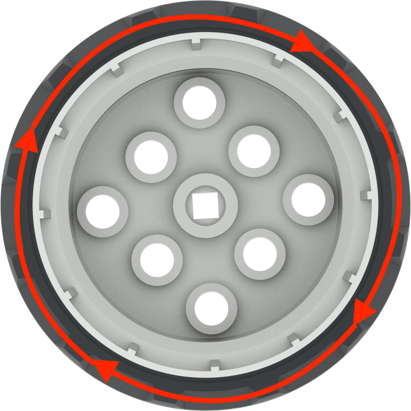 |
C = π d | ~ 160 mm or 6.25 in |
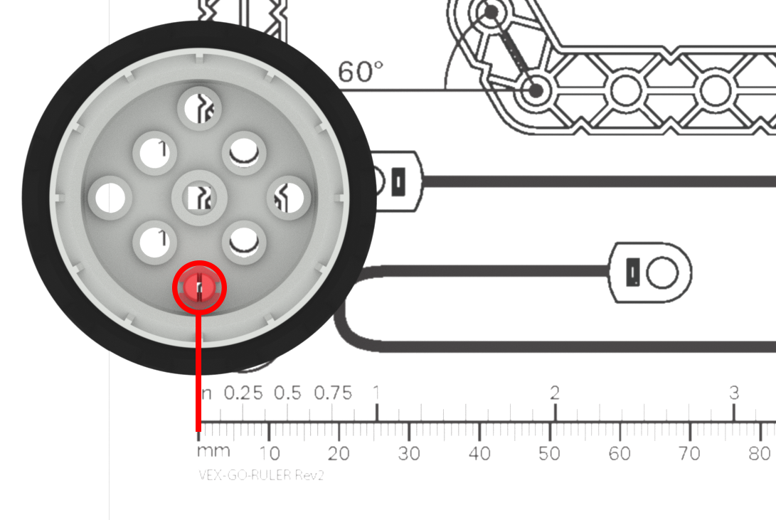
Measuring Accurately
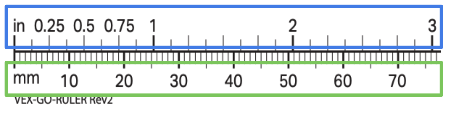
When students are measuring, be sure to guide them to measure carefully and precisely. You can use the VEX GO Printable Ruler for students to measure, or classroom rulers.
- Remind students to start measuring from the zero point on the ruler, and pay close attention to the end point of the object they are measuring. Starting or ending their measurements inaccurately will affect their calculations, and the eventual movement of their robot.
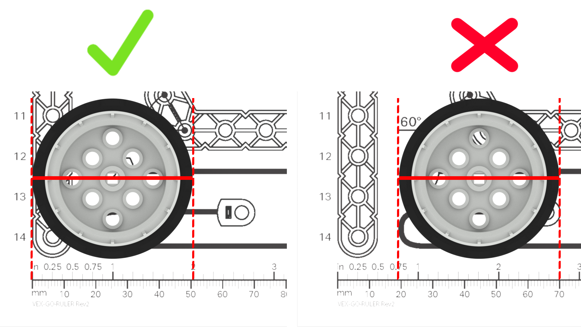
- Be sure that students know how to read the marks on the ruler they are using, in order to measure accurately. If the rulers you are using have both imperial and metric units (like the VEX GO Printable Ruler) be sure that students are consistently using the same units of measure.
- Students may round their measurements to the nearest unit, or fraction of a unit. Rounding can make calculations simpler, if needed; but can also make measurements less precise. For instance, you may instruct students to round up to the nearest half inch, or centimeter, but their robot moves slightly further than initially intended. Alternatively, you may have students measure to the nearest ⅛ of an inch, or millimeter, and find that their robots travel closer to the intended distance.
- If students need extra practice with measuring, you can use the Practice Measuring VEX GO Activity with individual students or groups, or as a whole class activity.
Mathematics of Turning 360°
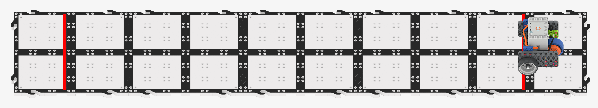
To complete the parade in Lab 5, students will drive their Code Base float along a parade route with a turn.
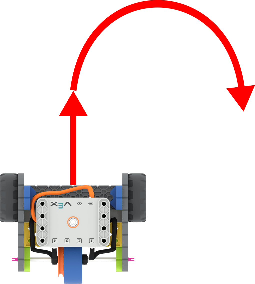
Code Base with arrows to show driving forward and then turning right
Students will build on what they learned about coding the robot to travel a straight line distance, to code the robot to drive a non-linear distance, or a turn. Students are still calculating the number of turns needed to travel a set distance, so they will use the same formula as in the previous Lab.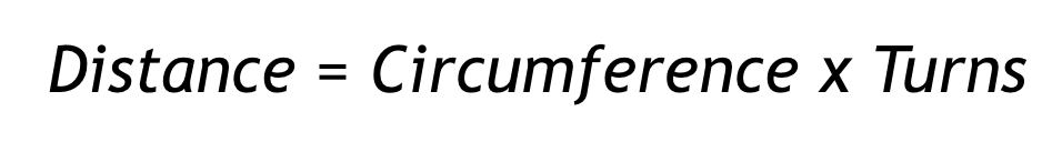
Watch the video below to learn about how to calculate the number of wheel turns needed to drive a 360° turn of the robot with your students.
Helpful References:
When the Code Base turns, the driving wheels move in opposite directions to turn the robot. For instance, to turn the robot to the right, the left wheel will drive forward, while the right wheel will drive in reverse.
Terminology and Values for the Code Base:
| Term | Definition | Visual | Formula | Value |
|---|---|---|---|---|
| Diameter | Measurement of a straight line from the center of each wheel (also known as the wheelbase) | 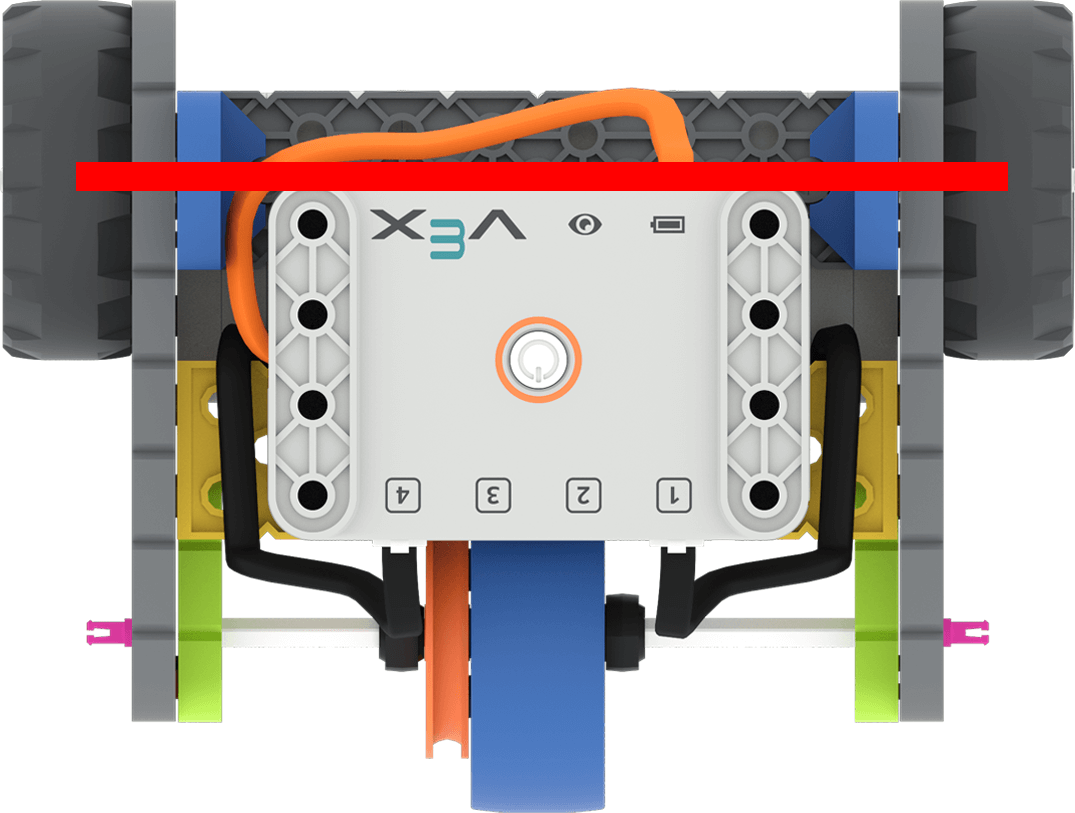 |
d = 2 r | ~ 135 mm or 5.3 in |
| Circumference | The total distance driven by the wheels in order to complete a 360° | 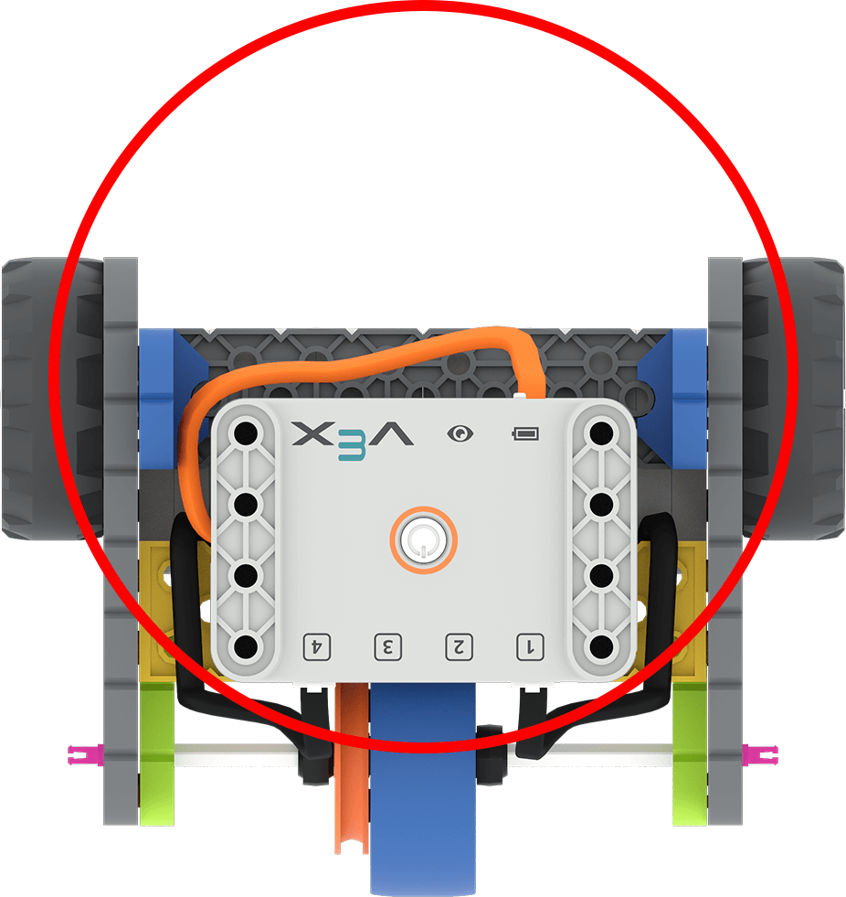 |
C = π d | ~ 424 mm or 16.7 in |
Mathematics of Turning Any Degree
Watch this video to learn more about calculating the number of wheel turns needed for the robot to turn any degree.
Converting to Degrees
The [Spin for] block will accept turns or degrees as parameters. To use degrees, simply multiply the number of turns by 360. This example shows the number of degrees the motors will spin in order to rotate the robot a full 360°. Note that in this project the motors are spinning in opposite directions, and the ‘and don’t wait’ is added to the first block, so the motors turn simultaneously. This will rotate the robot to the right for the desired 360°. 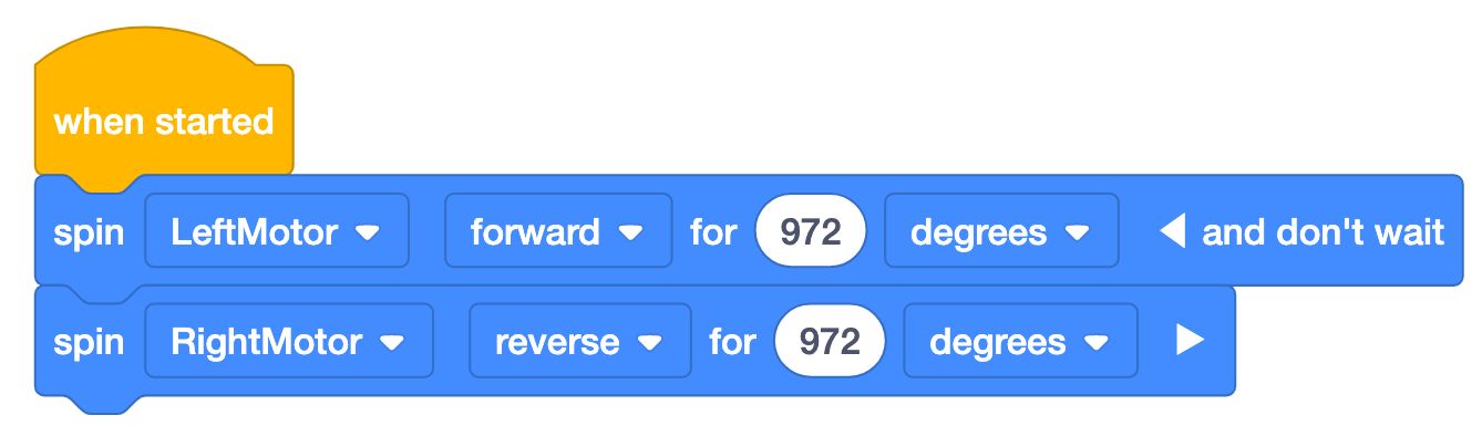
Common Misconceptions
There are several misconceptions that students can have about measuring and the mathematics of driving and turning. These are some of the most common, with suggestions for how to address them with your students.
| Situation | Misconception | Suggested Correction |
|---|---|---|
|
Teacher asks the class, what should we input in the [Spin for] block to make the robot turn 90°? Student responds “90”. |
The distance in degrees the wheel is driving to make a turn is equal to the turn angle. Students are not using the turning circumference of the robot to calculate the distance in degrees the wheel must drive. |
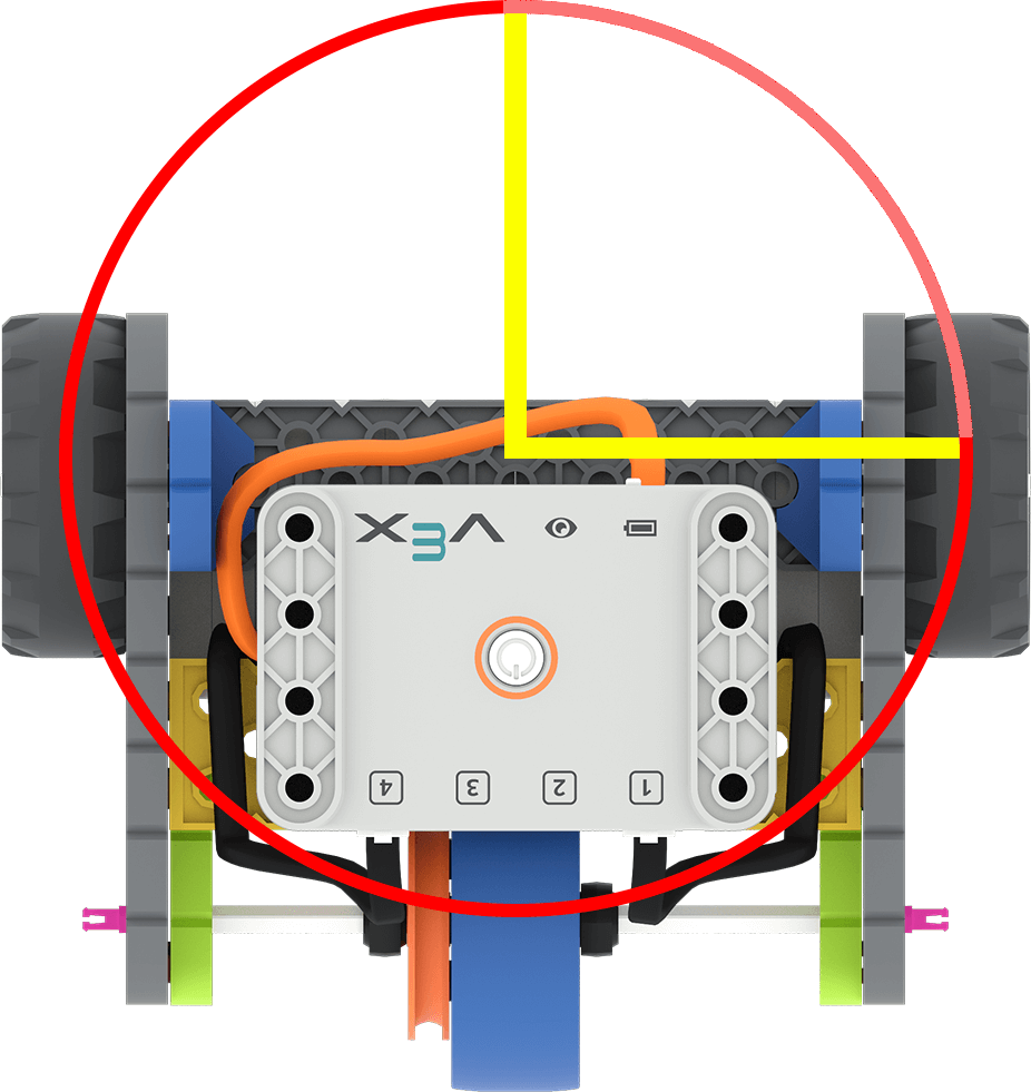
Remind students that the wheels need to drive along the turning circumference, in order for the robot to turn. (In this image, that is along the red circle from one yellow line to the other.)
Turn the wheel itself just 90°, to help students visualize how far the wheel turns to travel a given distance. |
|
Teacher asks the class, what should we input in the [Spin for] block to make the robot drive 12 inches forward? Student responds “12”. |
The number of wheel turns is equal to the desired drive distance. The student is not using the wheel circumference to calculate the number of wheel turns to drive the desired distance. |
Remind students of how far the robot moves with 1 wheel turn, and ask if 12 seems like too many or too few complete turns to drive 12 inches. To help students visualize this better, roll a wheel along a ruler for 12 wheel turns, to show students how far that distance is.
Remind students that 1 wheel turn is the wheel circumference, and that 12 inches must be divided by that circumference. |
| Student is measuring the wheel, but neither edge of the wheel is on the zero mark of the ruler. |
The ruler starts at 1, not zero. The student is not using the ruler correctly in order to get an accurate measurement. |
Remind students that the ruler starts at the ‘0’ mark, and that if they are not measuring from that point, their measurements will be incorrect. You may want to mark the start of the ruler with tape or a colored marker, as an extra visual aid for students as they are working. (For extra practice with measuring, students can complete the Practice Measuring Activity.) |
|
A student says their project is not working. The teacher notices that the correct number of wheel turns is in the [Spin for] block, but the parameter is set to ‘degrees’. |
Units or parameters are interchangeable. The students are not attending to the parameters/units of measure in their project. |
Ask students what unit of measure they are using, and if that matches the parameter in the block.
|
| A student tries to enter ‘21/4’ into the parameter of the [Spin for] block, to enter “2 ¼ turns”. |
Fractions and decimals are written the same way. The student is not converting the fraction to a decimal. |
Remind students that they need to convert fractions to decimals in order for them to be recognizable parameters. To do this, divide the numerator by the denominator. 2 ¼=94 =2.25 You may want to have students chart frequently used fractional values and their decimal equivalents to create their own resource. |
|
Teacher asks the students to share their wheel circumference calculation. Student answers |
Circumference is calculated using the radius -πxradius. The student is using the wrong measurement in the calculation. |
Remind students that the circumference is π x diameter; and the diameter is a straight line across the center of the wheel (or twice the radius).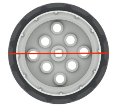 You may want to measure and calculate value as a whole class activity if many students are having difficulty with using the formulas. |
 Remind students that their calculations will only work as intended if the parameter is set to the correct unit. Turns and degrees are not the same value.
Example Solutions
Lab 4 Example Solution
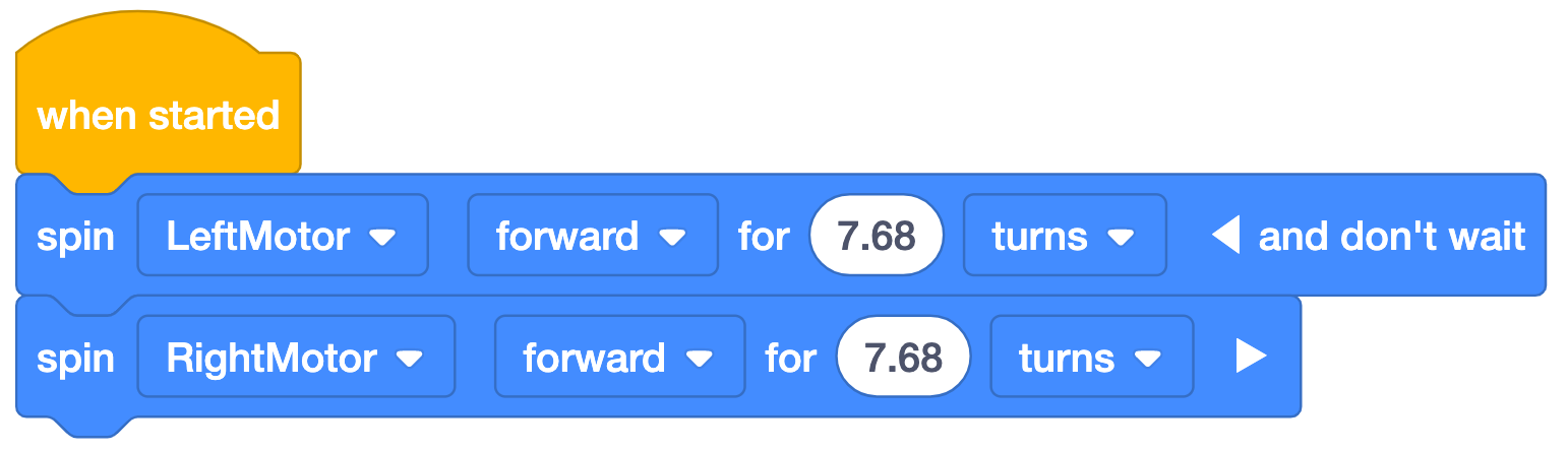
*Note: The 'and don’t wait’ is used with the first block in the example project so that both blocks will execute simultaneously. Without ‘and don’t wait’, the first motor would spin, then the second, and the Code Base would not drive as intended. Be sure students' do NOT collapse the 'and don't wait' or their project will not run as intended.
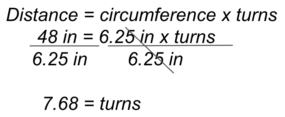
To drive the 48 inch (~122 cm) length of the parade route, the Code Base will need to travel ~7.68 turns. The calculation is shown on the left, and the example VEXcode GO solution on the right.
Lab 5 Example Solution
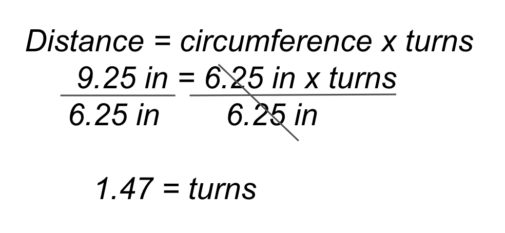
To drive the 48 inch (~122 cm) length of the parade route and turn 180 degrees, the Code Base will need to travel forward for ~7.68 turns, then spin one motor forward and the other reverse for ~ 1.47 turns. The calculation is shown alongside the example VEXcode GO solution on the right.
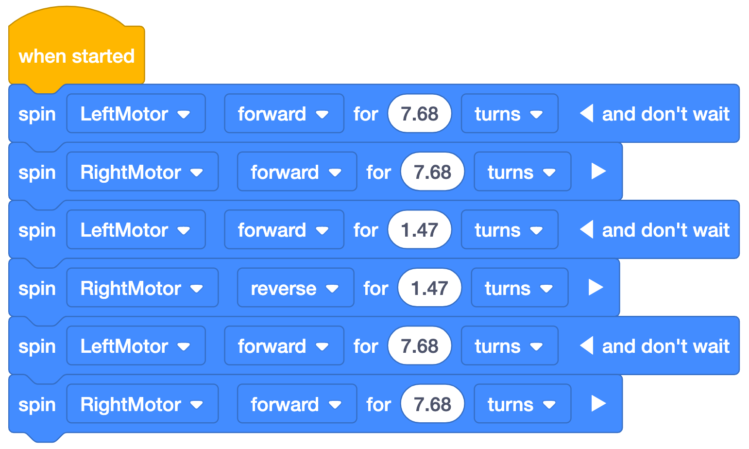
Note: To use degrees instead of turns, multiply the turn calculations by 360.
Extension Parade Route
If students need an extra challenge, you can extend the parade route in many different ways. This is one example, with a possible solution.
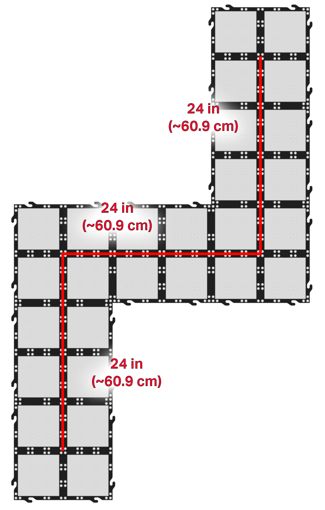
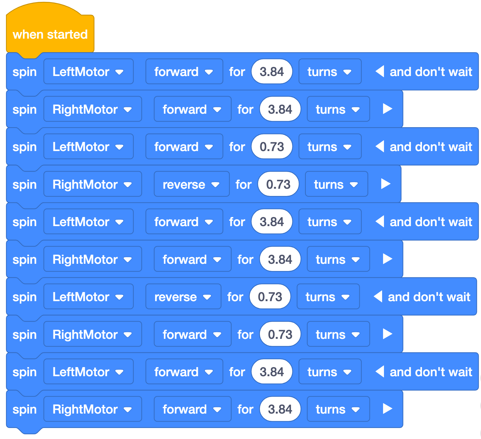
In this example route, the driving distances and turns are halved from the Labs. In this route however, the direction of the turns matter. In addition to recalculating, students will have to figure out the directions to spin the wheels to turn in the desired direction.
The halved calculations from previous Labs are as follows:
Driving distance = ~ 3.84 turns
Turning distance = ~ 0.73 turns
These values are used in the following example VEXcode GO solution: