
In Lesson 2, you learned how to find a waypoint to code a controlled path for the 6-Axis Robotic Arm to avoid an obstacle. In this Lesson, you will practice finding waypoints to avoid multiple obstacles. At the end of this Lesson, you will use the waypoints you found to code the 6-Axis Arm to move and draw a path between obstacles.

Multiple Waypoints
In many situations and industry settings, robotic arms will need to travel and move around multiple obstacles. You can use strategies that you have previously learned in order to find these waypoints. To practice this, follow along with these steps.
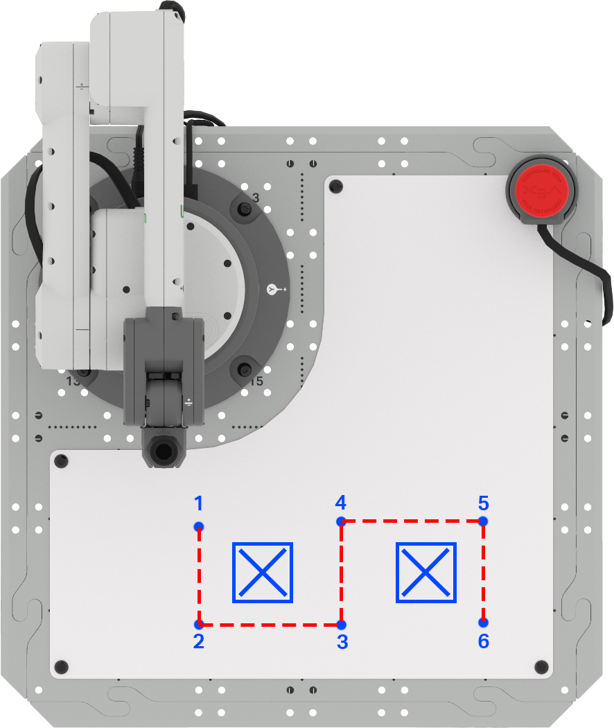
Begin by setting up your space with two "keep out" areas marked on the Whiteboard Attachment with a whiteboard marker. These should be roughly the size of a Cube.
Sketch this layout in your engineering notebook.

Your 6-Axis Arm will need to draw a line to follow the path provided here. Document the path in your engineering notebook.

Label each waypoint needed on your Whiteboard. Document these waypoints in your engineering notebook.
In the next step, you will need to determine the (x, y, z) coordinates of each waypoint. This can be done using the formula from Lesson 2, or you can use the Monitor Console to collect each of these coordinates.
For Your Information
When using the formula to calculate the unknown coordinates of a waypoint, the direction the 6-Axis Arm needs to travel along an axis is important. If the 6-Axis Arm will move in the positive x or y direction, the value of ∆x or ∆y will be positive. If the 6-Axis Arm will move in the negative x or y direction, the value of ∆x or ∆y will be negative.
For instance, when moving from waypoint 3 to waypoint 4, the 6-Axis Arm will move along the x-axis in the negative direction.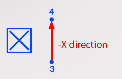
When using the formula, the value for ∆x will be negative. In this example, the x-coordinate of point 3 is 195mm, and the distance between points 3 and 4 was measured to be 105mm. Using the formula, we can calculate the x-coordinate of point 4 to be 90mm, as shown here. 
You previously used the Monitor Console in Unit 3.
To open the Monitor Console in VEXcode EXP, select the Monitor icon. Ensure that your 6-Axis Arm is connected to VEXcode EXP.

Manually move the end of the 6-Axis Arm to each waypoint and record the corresponding (x, y, z) coordinate in your engineering notebook.

Now that you have your coordinates for each waypoint, you need to edit the VEXcode project from the Lesson 2.
Open your project in VEXcode EXP. This project should include the following blocks, but may have different coordinate values.

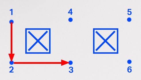
Enter the coordinates of the waypoints 1, 2, and 3 into the three Move to position blocks in order. Be sure to use your coordinates.
Note: You can edit the Comment blocks to match the project, by selecting the space and typing.

Look at the blocks in the project. What do you think the 6-Axis Arm will do when the project is run? Document your prediction in your engineering notebook.

Be sure the 6-Axis Arm is connected to VEXcode. Run your project.
Observe the behavior of the 6-Axis Arm. Does it move as you predicted it would?

Stop the project once the 6-Axis arm has finished moving.
The 6-Axis Arm should move from waypoint 1, to 2, and end at waypoint 3. If it does not, go back and check the coordinates you put into the project. Be sure the x, y, and z-parameters match the coordinates you gathered in your engineering notebook. Run the project again to test it.
Once you have successfully navigated to waypoint 3, move on to the next step.
Add three Move to position blocks to the stack, so you have a total of six – one for each waypoint, as well as your starting and ending location.

For Your Information
You can also add blocks by duplicating what is already in a stack. In order to duplicate, open the Context Menu by right clicking on the block you want to duplicate. When duplicating, every block beneath the one you select will be duplicated.
In this project, you can select the first Move to position block in order to duplicate all three for a total of six. Once 'Duplicate' has been selected, the blocks will be copied (including their parameters) and you can add them to the bottom of the stack.
In this video, the Comment blocks and the Move to position blocks are duplicated by right clicking to open the contex menu, and selecting the top option, 'duplicate'. The duplicated blocks are attached to the bottom of the project. You can edit the Comment blocks in your project to help keep your project organized.
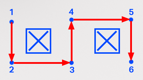
Input the coordinates for the last three waypoints into the last three Move to position blocks. Be sure to input the coordinates from your engineering notebook in order, ending with the final location.
Note that your coordinates will vary from the ones shown here because they are based on the exact location of your obstacles and the coordinates you gathered.

Be sure the 6-Axis Arm is connected to VEXcode. Run your project.
Observe the behavior of the 6-Axis Arm. Does it move as you predicted it would?

Stop the project once the 6-Axis Arm has completed its movements.
The 6-Axis Arm should move from waypoint 1, through waypoints 2 through 5, and end at waypoint 6. If it does not, go back and check the coordinates you put into the project. Be sure the x, y, and z-parameters match the coordinates you gathered in your engineering notebook. Run the project again to test it.
Once you have successfully navigated to waypoint 6, move on to the next step.
Rename and save the project to your device.

Activity
Now that you have learned how to find multiple waypoints and code the 6-Axis Arm to navigate a path, you are going to practice this skill in the activity. In this activity, you will code the 6-Axis Arm to move along the designated path to avoid the obstacles.
- Setup:
- Draw three 'keep out' locations on the Tile as shown in this image.
- Label your starting and ending locations A and B as shown.

Activity:
- Code the 6-Axis Arm to move from point A to point B along the path as shown above.
- Record your process for finding waypoints in your engineering notebook.
- After building and testing your project, run it to ensure the project works as intended.
- Once you have completed the activity, rename and save your project to your device.
Check Your Understanding
Before moving to the next Lesson, ensure that you understand the concepts in this Lesson by answering the questions in the document below in your engineering notebook.
Check Your Understanding questions > (Google Doc / .docx / .pdf)
Select Next > to apply your skills in the Putting It All Together activity.