
In the previous Lessons, you learned how to draw a triangle through finding missing coordinates. In this Lesson, you will learn what to do when the 6-Axis Arm moves along the x or y-axes in the negative direction, and how to calculate missing coordinates.
At the end of this Lesson, you will draw a diamond by connecting the coordinates you have determined.
Finding Missing Coordinates
In Lesson 3 you determined the missing coordinates of a triangle based on knowing one point of the triangle and two side lengths. You will now build on that project to draw a second triangle.
Finding Point D
Sketch the known information in your engineering notebook.
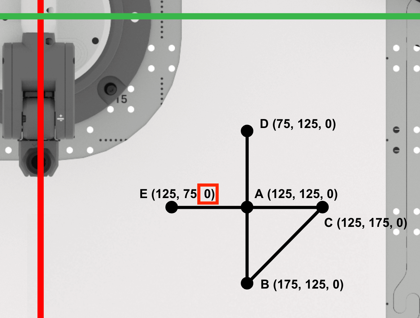
Triangle ABC is located at points:
- A (125, 125, 0)
- B (175, 125, 0)
- C (125, 175, 0)
This was the triangle you drew in Lesson 3.
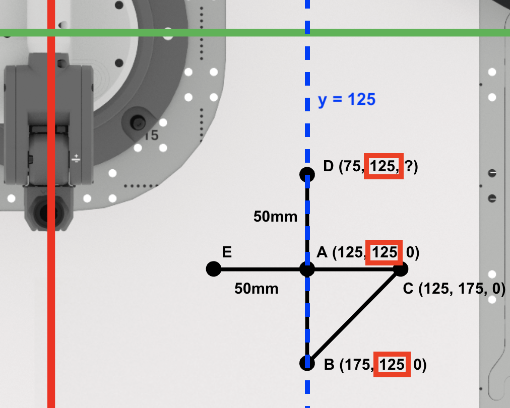
The second triangle, ADE has side lengths of 50mm, for sides AD and AE. The sides of triangle ADE are shown in this image with blue lines and text.
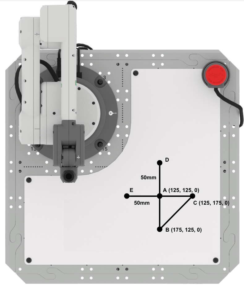
Side AD of right triangle ADE, is parallel to the x-axis.
Note that as you move from point A to point D along the x-axis, the x-coordinates get lower in value. This will be reflected in the equation used to calculate the x-coordinate of point D.
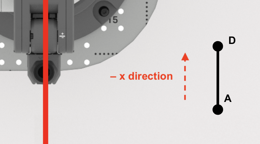
Find the x-coordinate of point D.
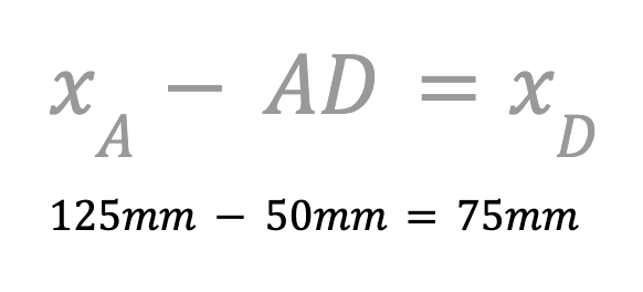
Because the 6-Axis Arm will move in the negative direction along the x-axis, you need to use subtraction. Subtract the length of AD from the x-coordinate of point A to find the x-coordinate of point D.
The x-coordinate of point D is 75mm. Record this in your engineering notebook.
Next, we will find the y-coordinate of point D.
Since points A, B, and D are along the line y=125mm, the y-coordinate of point D is the same as points A and B (125mm). Record this in your engineering notebook.
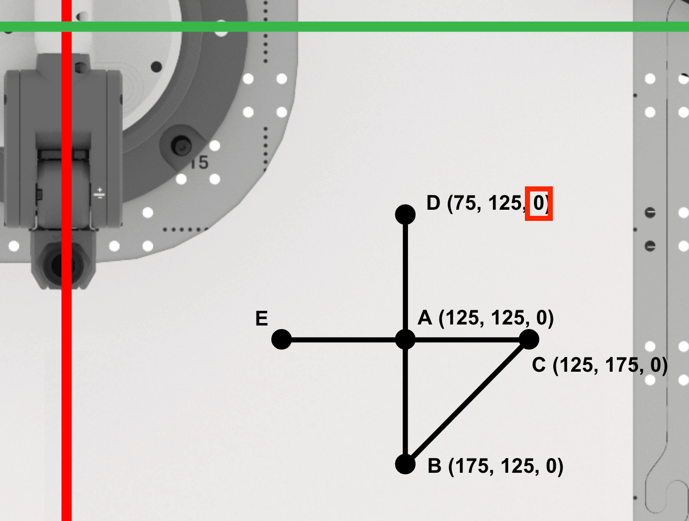
Since the Pen is not raising between points A and D, the z-coordinate of point D will remain zero.
Point D is (75, 125, 0). Record this in your engineering notebook.
Finding Point E
Find the x-coordinate of point E.
Since points A, C, and E are along the line x=125mm, the x-value of point E is the same as points A and C (125mm).
Record this in your engineering notebook.
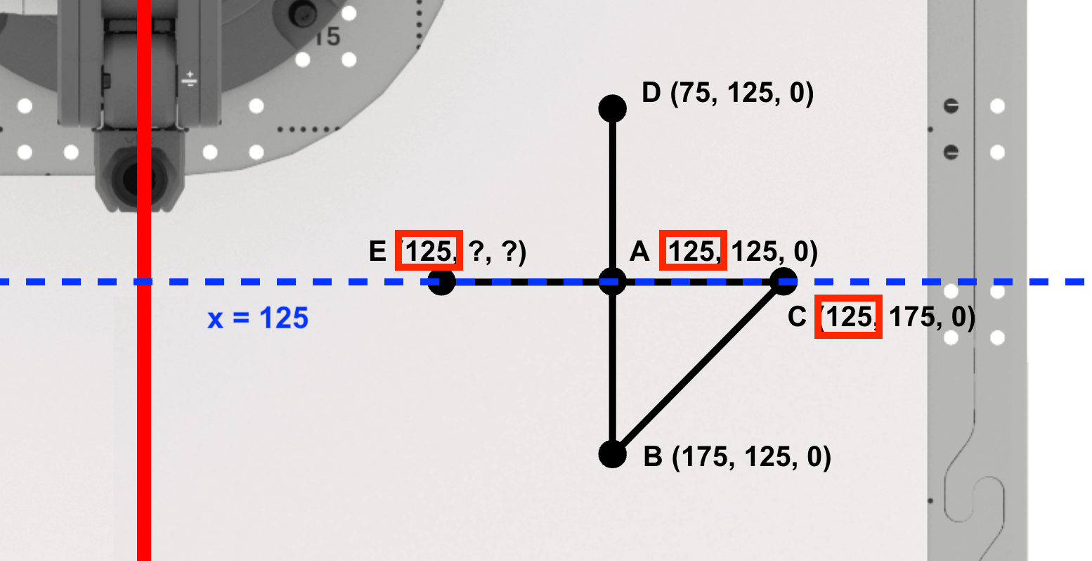
Side AE of the right triangle ADE, is parallel to the y-axis.
Note that if you move from point A to point E along the y-axis, the y-coordinates get lower in value. This will be reflected in the equation used to calculate the y-coordinate of point E.

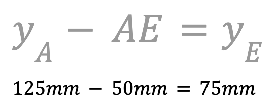
Next, find the y-coordinate of point E.
Because the 6-Axis Arm will move in the negative direction along the y-axis, you need to use subtraction. Subtract the length of AE from the y-coordinate of point A to find the y-coordinate of point E.
The y-coordinate of point E is 75mm. Record this in your engineering notebook.
Since the Pen is not raising between points D and E, the z-coordinate of point E will remain zero.
Point E is (125, 75, 0). Record this in your engineering notebook.
Coding the 6-Axis Arm to Draw Triangle ADE
Now that you have determined the coordinates for points D and E, it is time to create a VEXcode EXP project for the 6-Axis Arm to connect points A, D, and E in order to draw another triangle.
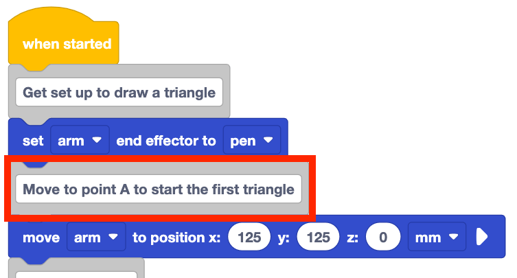
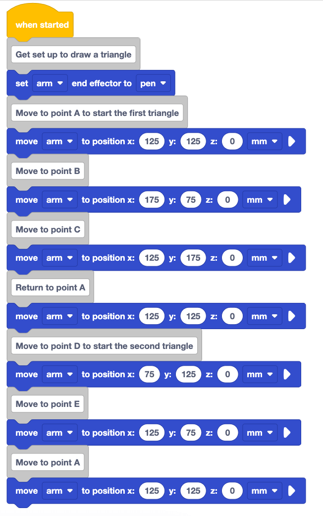
Open the Unit 5 Lesson 3 project to draw triangle ABC on the Whiteboard, or recreate the project as shown here.

Change the Comment block shown here to "Move to point A to start the first triangle."
Because you are drawing two triangles, the comment can be changed to provide context on what blocks in the project are used to draw the first triangle versus the second triangle.
Add a Comment block to the bottom of stack and type in "Move to point D to start the second triangle."
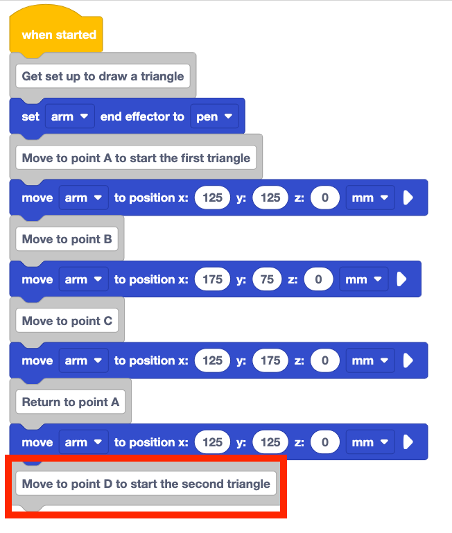
Add a Move to position block to the stack underneath the Comment block.
Set the Move to position block's parameters to point D's coordinates, documented in your engineering notebook.

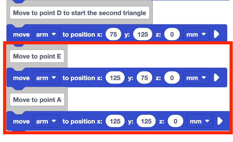
Add Comment blocks and Move to position blocks for point E and the return to point A to complete the second triangle.
Set the parameters of the Move to position blocks to the coordinates of points E and A, that were recorded in your engineering notebook.
Be sure to rename and save your project to your device.

Your full project should look like this when completed.
When you have finished building your project, be sure the 6-Axis Arm is connected to VEXcode EXP and run the project.
Stop the project when the 6-Axis Arm has finished drawing the two triangles.
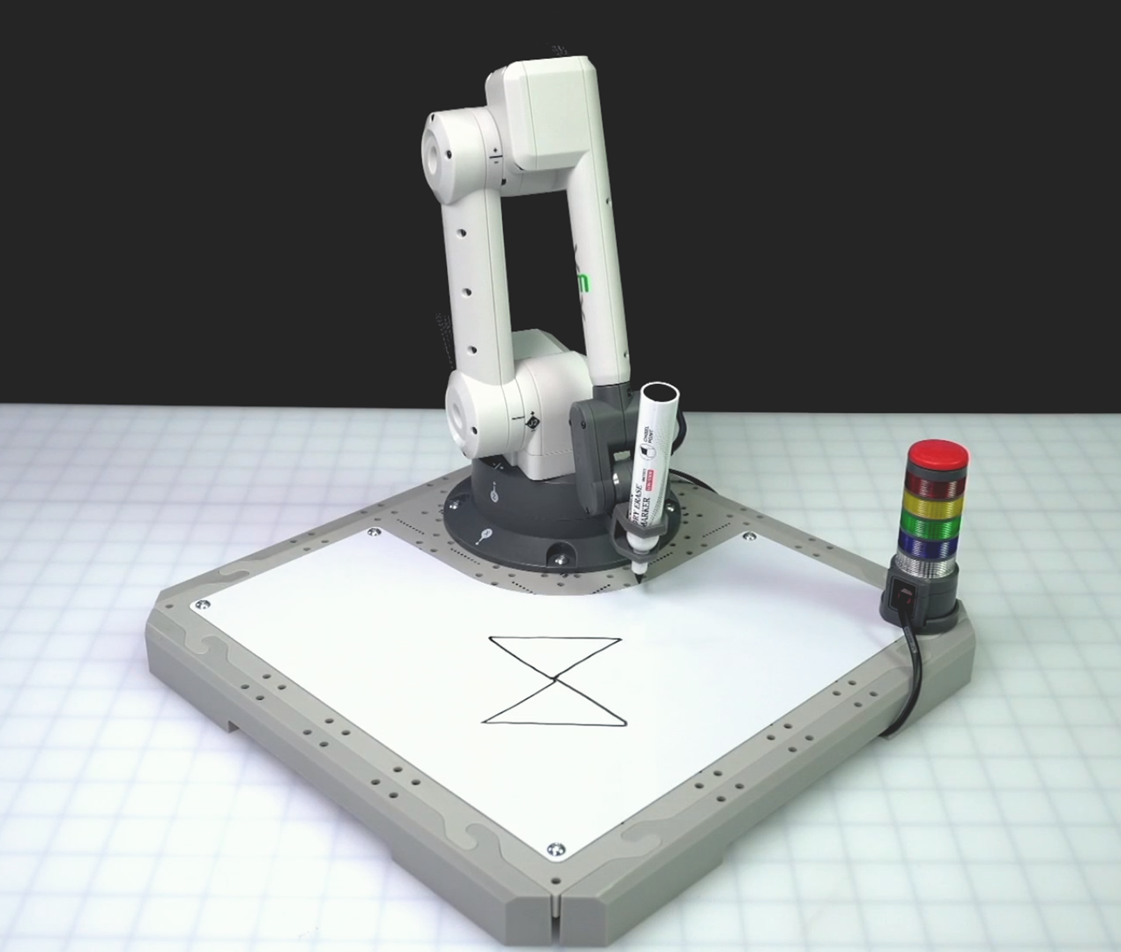
The 6-Axis Arm will draw triangle ABC as it did in Lesson 3. Then it will move to point D, to draw the first side of triangle ADE. Then the 6-Axis Arm will move from point D to point E to complete the second side of triangle ADE, and will finish the triangle by moving pack to point A.
Note: This image shows the 6-Axis Arm having been manually moved after the project was stopped so that both triangles can be clearly seen.
Activity
In this Lesson you have learned how to draw triangles with sides that require moving in the negative direction along the axes. Now you will apply your learning to draw a diamond, made up of four triangles.

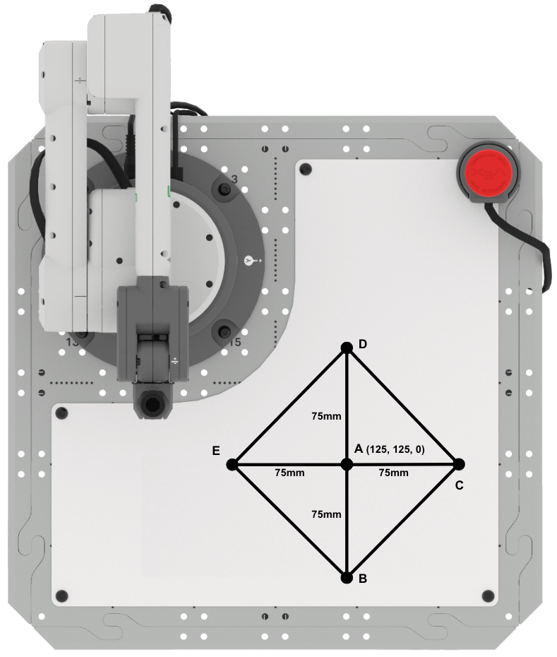
- Setup: Draw points A, B, C, D, and E in your engineering notebook as shown above.
- Point A is located at (125, 125, 0)
- Side lengths AB, AC, AD, and AE are 75mm
- Activity:
- Use the formulas from Lessons 3 and 4 to determine the coordinates of points B, C, D, and E above. Record the coordinates in your engineering notebook.
- Create a VEXcode EXP project to connect the points and draw the shape shown above.
- You can build off of the Lesson 4 project, or download the Signal Tower Template project.
- Be sure to set the Set end effector block to pen to get started.
- Use Comments to communicate the behaviors of the 6-Axis Arm in your project.
- When you have finished building your project, run the project to test it.
- Did your project draw the diamond shown above? If not, continue to modify your project and test it until you are successful.
- After you have completed the project, rename and save the project to your device.
Check Your Understanding
Before moving to the next Lesson, ensure that you understand the concepts in this Lesson by answering the questions in the document below in your engineering notebook.
Check Your Understanding questions > (Google Doc / .docx / .pdf)
Select Next > to complete the Putting It All Together activity.