
In the previous Lessons, you learned how to draw a triangle on the Whiteboard with the Pen Holder Tool where all the points of the triangle were given. However, if some points of the triangle are not given, they will need to be determined mathematically in order for the 6-Axis Arm to move in multiple axes.
In this Lesson, you will find two missing coordinates of a triangle in order to draw the triangle. At the end of this Lesson, you will apply what you have learned to build onto the triangle to draw a square.
Finding Missing Coordinates
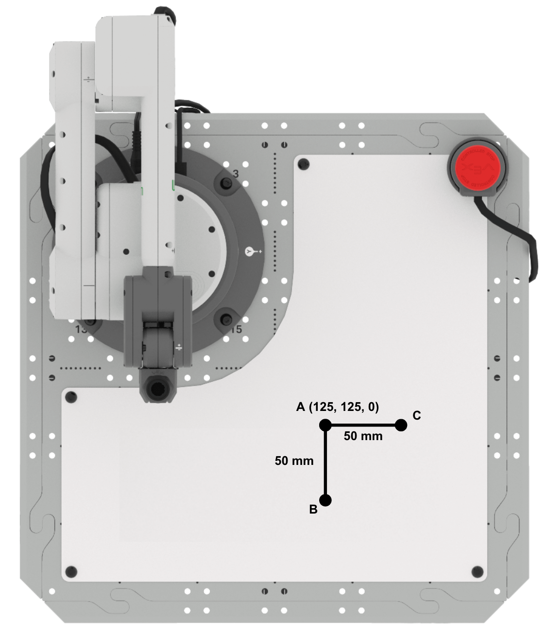
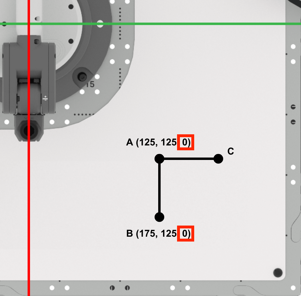
The 6-Axis Arm is going to draw a triangle. Here is the information we know about this triangle:
- Point A is (125, 125, 0).
- Each side length is 50mm.
- Triangle ABC is a right triangle (a triangle with one 90 º angle).
- The side opposite this angle is the longest side, known as the hypotenuse. The other two sides are called the legs.
Using this information, we can find the two endpoints (points B and C) to draw the triangle.
Follow along with the steps below to find points B and C and draw the triangle.
Finding Point B
Sketch the known information about the triangle in your engineering notebook.
Point A is located at approximately (125, 125, 0).
The distance from point A to point B is approximately 50mm. The distance from point A to point C is approximately 50mm. Each of these distances corresponds to the side lengths of the triangle.
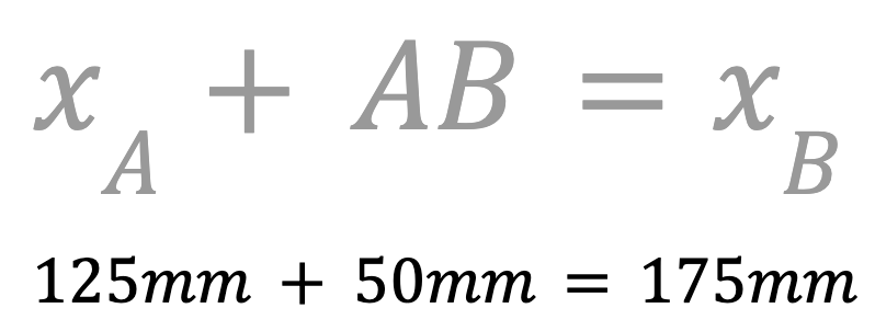
Determine the x-coordinate of point B. This can be done by adding the length of AB to the x-coordinate of point A to find the x-coordinate of point B.
The x-value of point B is 175mm. Record this in your engineering notebook.
Next, we will find the y-coordinate of point B.
Since points A and B are along the line y=125mm, the y-coordinate of point B is the same as point A (125mm). Record this in your engineering notebook.
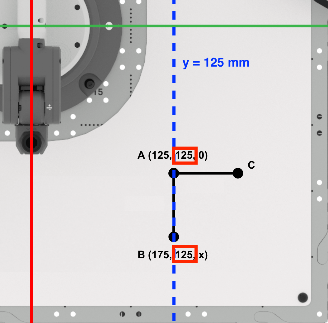
Since the Pen is not raising between points A and B, the z-coordinate of point B will remain zero.
Point B is (175, 125, 0). Record this in your engineering notebook.
Finding Point C
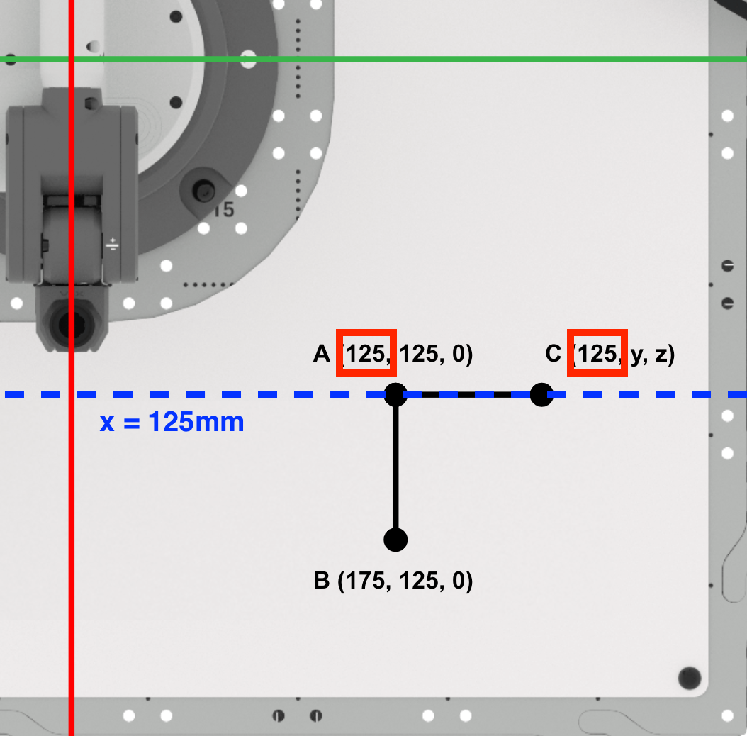
Find the x-coordinate of point C.
Since points A and C are along the line x=125mm, the x-value of point C is the same as point A (125mm).
Record this in your engineering notebook.
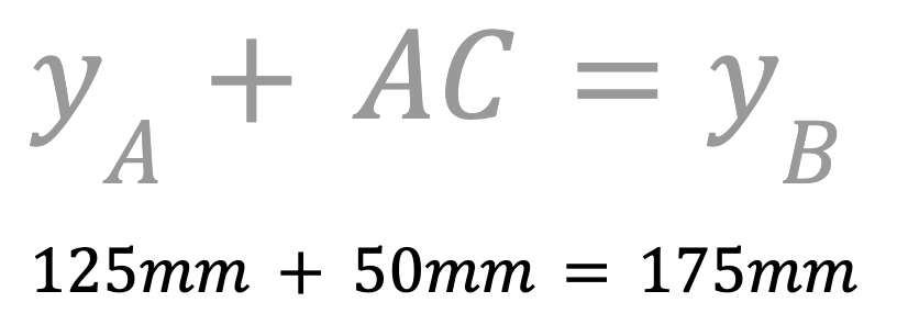
Next, find the y-coordinate of point C.
Since we are drawing a right triangle, we know that side AC will be parallel to the y-axis. Add the length of AC to the y-coordinate of point A to find the y-coordinate of point C.
The y-coordinate of point C is 175mm. Record this in your engineering notebook.
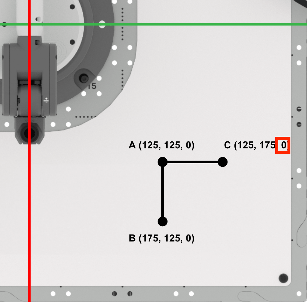
Since the Pen is not raising between points A and C, the z-coordinate of point C will remain zero.
Point C is (125, 175, 0). Record this in your engineering notebook.
Coding the 6-Axis Arm to Connect Points A, B and C
Now that you have determined the coordinates for points B and C, it is time to create a VEXcode EXP project for the 6-Axis Arm to connect points A, B and C in order to draw a triangle.
Open a New Blocks Project by following the steps in this video. In the video clip, File is selected in the Toolbar, and then New Block Project is selected. A dialog box pops up with two options, EXP Brain on the left, and Arm on the right. The Arm option is selected, and a new project opens in the Workspace.
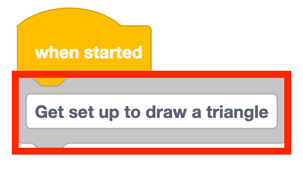
Add a Comment block to the stack and type in 'Get set up to draw a triangle.'
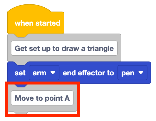
Add a Set end effector block to the stack and set it to 'pen.'

Add a Comment block to the stack and type in 'Move to point A.'
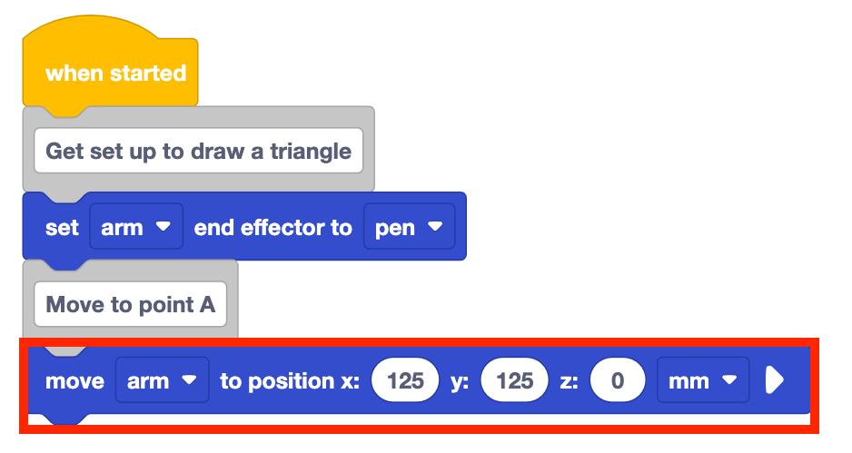
Add a Move to position block to the stack underneath the Comment block.
Set the Move to position block's parameters to point A's coordinates, documented in your engineering notebook.
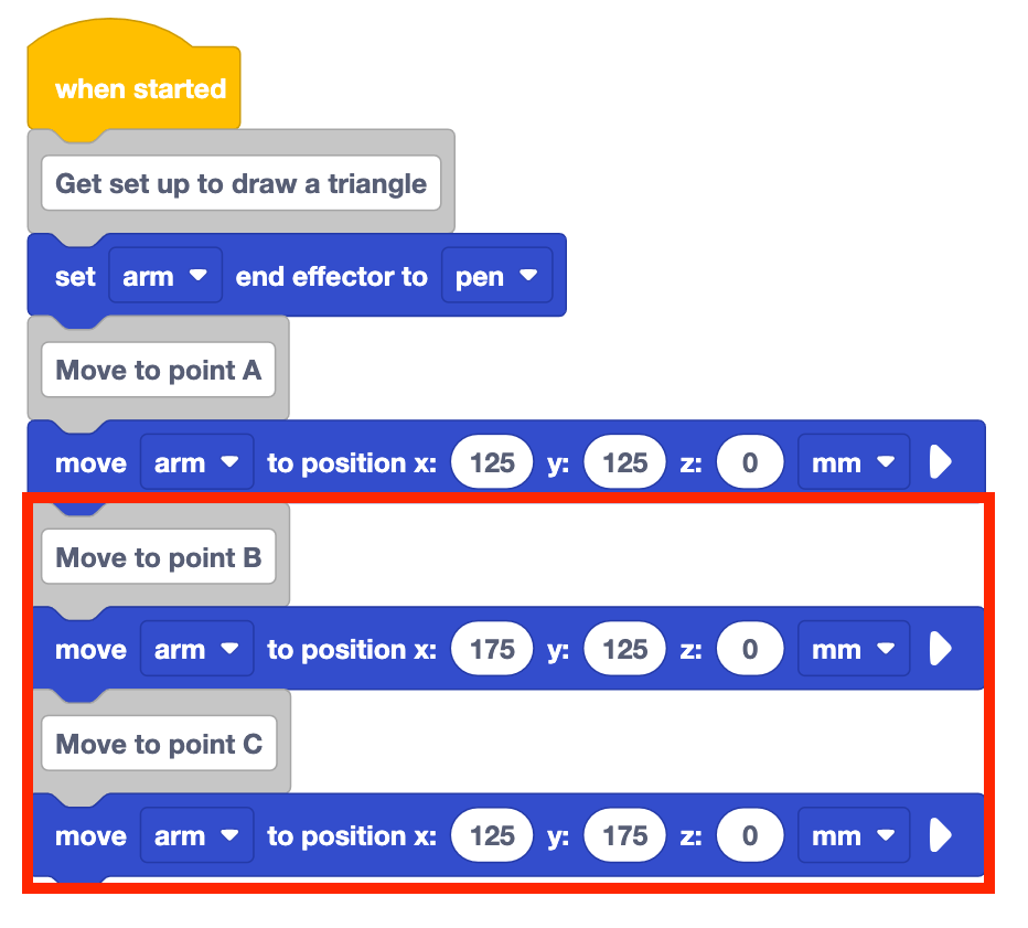
Add Comment and Move to position blocks for points B and C.
Set the parameters of the Move to position blocks to the coordinates of points B and C, that were recorded in your engineering notebook.
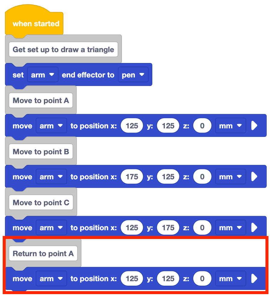
The project as is will only draw two sides of the triangle. The 6-Axis Arm needs to go back to point A to complete the triangle.
Add a Comment block to the stack and label it 'Return to point A' as well as adding a Move to position block.
Set the parameters of the Move to position blocks to the coordinates of point A.
Be sure to rename and save your project to your device.

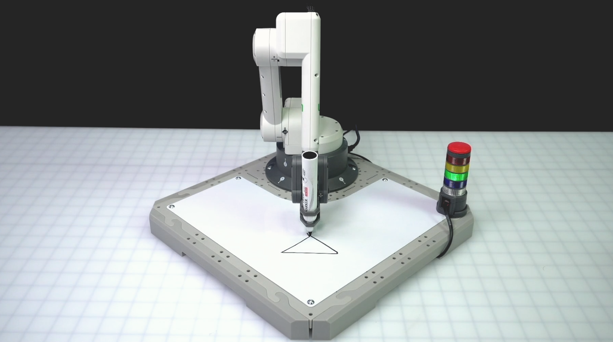
Be sure the 6-Axis Arm is connected to VEXcode. Run your project.
The 6-Axis Arm will start at point A, then move to point B to draw the first side of the triangle. It will then continue to point C, drawing the second side of the triangle. The 6-Axis Arm will then move back to point A to complete the triangle by drawing the third side.
Stop the project once the 6-Axis Arm has finished moving.
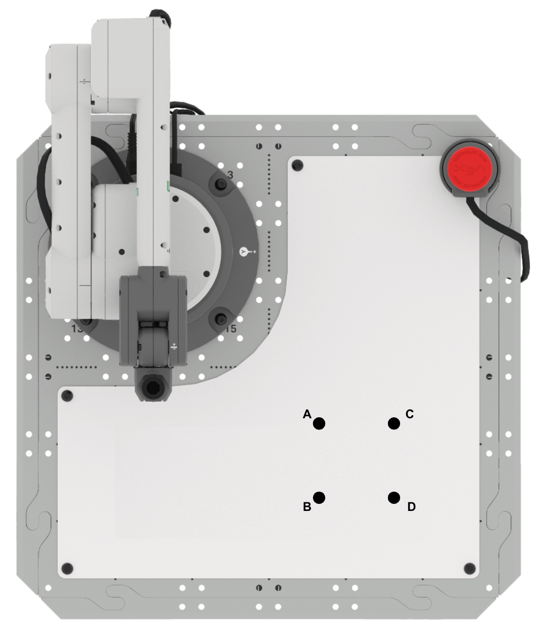
Activity
Now that you have learned how to find missing coordinates given an initial coordinate and two side lengths, you will practice this skill. In this activity, you will build on your project from this Lesson to draw a square.

- Setup: Draw points A, B, C, and D in your engineering notebook as shown above. You can use the information about triangle ABC from this Lesson to help you find the missing point D.
- Point A is located at (125, 125, 0)
- Point B is located at (175, 125, 0)
- Point C is located at (125, 175, 0)
- Side lengths AB and AC are 50mm
- Activity: Find the coordinates of point D. Build onto your project from this Lesson to draw a square.
- Once you have edited your project, run it to test. Does the 6-Axis Arm successfully draw all four sides of the square? If not, modify your project and test it again.
- Record the process you used to find point D in your engineering notebook, and include details about how you used point D in your VEXcode project.
Check Your Understanding
Before moving to the next Lesson, ensure that you understand the concepts in this Lesson by answering the questions in the document below in your engineering notebook.
Check Your Understanding questions > (Google Doc / .docx / .pdf)
Select Next > to learn how to draw more triangles in different orientations.