
In the previous Unit, you moved the 6-Axis Arm to various waypoints around an obstacle by moving individually along the x and y-axes. In this Unit, you will build on that to incorporate movement along multiple axes simultaneously. Using the Pen, you will be able to see the path of the 6-Axis Arm as it draws shapes with diagonal lines, like a triangle.
In this Lesson, you will:
- Learn about multi-axis movement as it relates to the 6-Axis Arm.
- Look at a project and predict the movement of the 6-Axis Arm.
- Compare your prediction to the actual movement of the 6-Axis Arm.
Moving Along Multiple Axes
When you coded the 6-Axis Arm to move to various waypoints in the previous Unit, you moved along the x and y-axes individually. This was important to enable you to move around the obstacles in place. 
However, it is important to note that this is not always the quickest way to move from one point to another. If there was no obstacle in the image above, you could move directly from point 1 to point 3 by moving diagonally.
To do this, the 6-Axis Arm would need to be moving on both the x and y-axes at the same time. In this Lesson you will look at a project designed to move the 6-Axis Arm along multiple axes, to help you better understand how the 6-Axis Arm moves in 3D space.
Look at the blocks in this project. Think about what you've learned about how the 6-Axis Arm moves. What do you think the 6-Axis Arm will do when this project is run?
Record your prediction in your engineering notebook. Describe the movement of the 6-Axis Arm in words. Draw what you think the Pen on the 6-Axis Arm will draw.
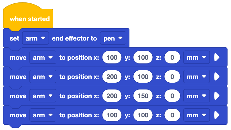
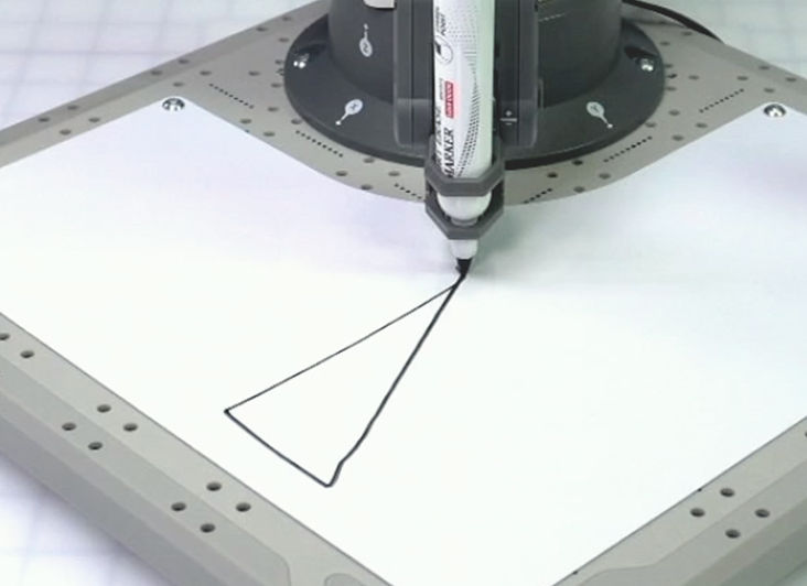
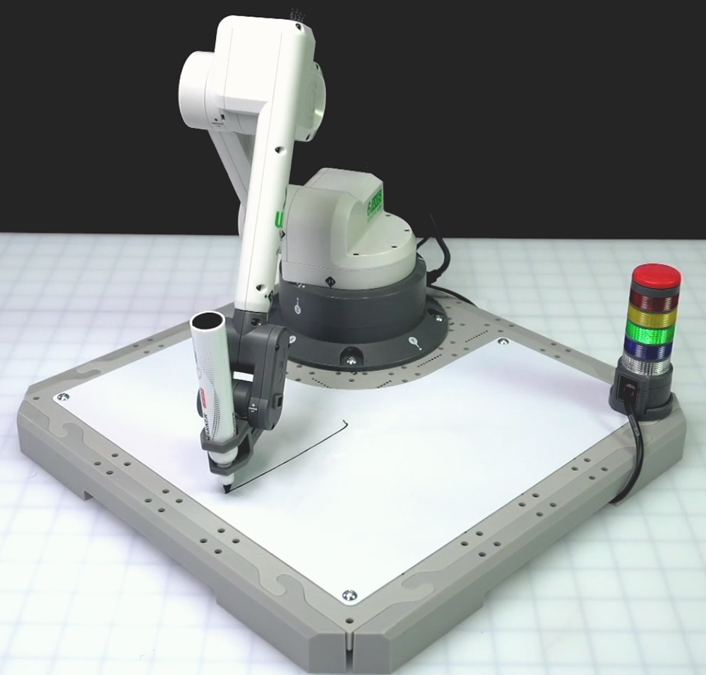
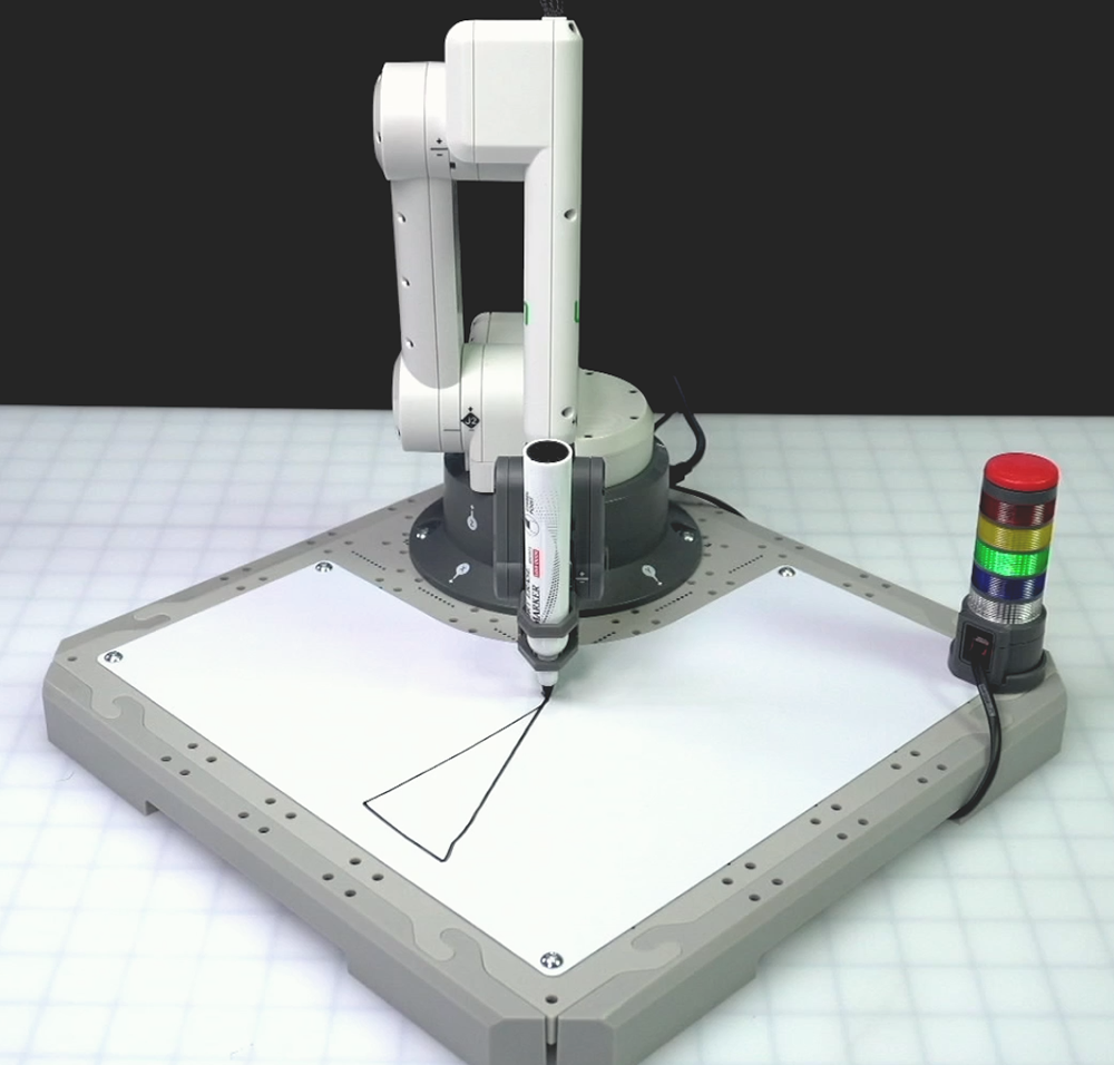
Watch this video to see this project in action. Observe the behavior of the 6-Axis Arm. In the video, the 6-Axis Arm moves from the safe position to coordinate (100, 100, 0), then moves to each of the four coordinates to draw a triangle.
Does the actual movement of the 6-Axis Arm match your prediction? Why or why not?
Does the Pen draw something similar or different to what you drew in your engineering notebook? If it is different, why do you think that is?
Identifying the Movements in the Project
Now let's break down the behaviors you observed in relation to how the 6-Axis Arm moves along the x and y-axes. The first two movements are similar to how you navigated the 6-Axis Arm around obstacles, while the third movement is different.
To draw the first side of the triangle, the 6-Axis Arm moves along the x-axis.
If we look at the coordinates in the project, the 6-Axis Arm begins at (100, 100, 0) and moves to (200, 100, 0). Only the x-coordinate changes, indicating motion along just the x-axis.
To draw the second side of the triangle, the 6-Axis Arm moves along the y-axis.
Looking at the coordinates in the project again, the 6-Axis Arm begins this line at (200, 100, 0) and moves to (200, 150, 0). Now only the y-coordinate changes, indicating motion along just the y-axis.

To draw the third side of the triangle, the 6-Axis Arm moves in a diagonal line. It is moving along both the x and y-axes in order to return back to the starting coordinate of the triangle.
Using the coordinates in the project, we can see that the 6-Axis Arm begins this last line at (200, 150, 0) and moves to (100, 100, 0). Now both the x and y-coordinates change, indicating motion along both axes at the same time.
Using the Monitor Console, you can see how the x and y-values change one at a time for the two sides of the triangle, and then both at the same time for the third side. Watch this video to see the x and y values change inside the Monitor Console in real time.
In the next Lesson, you will learn how to build a project to code the 6-Axis Arm to draw a triangle for yourself.
Check Your Understanding
Before moving to the next Lesson, ensure that you understand the concepts in this Lesson by answering the questions in the document below in your engineering notebook.
Check Your Understanding questions > (Google Doc / .docx / .pdf)
Select Next > to learn how to build this project yourself.