
In this Lesson, you will learn about the Cartesian coordinate system used with the 6-Axis Robotic Arm.
At the end of this Lesson, you will use your understanding of the Cartesian coordinate system and its relation to the 6-Axis Arm to estimate coordinates of three CTE Tile locations.
Cartesian Coordinate System
In order to move the 6-Axis Arm in space, we need to have a common frame of reference so the 6-Axis Arm can move to the desired location. The 6-Axis Arm uses the Cartesian coordinate system in order to determine where the end of the 6-Axis Arm is located.
X, Y, and Z-Axes
A coordinate system is a mathematical grid of values. There are different types of coordinate systems, but the Cartesian coordinate system is used with the 6-Axis Arm. This is also known as a 3D (Dimensional) system, since its three dimensions are the x, y, and z-axes.
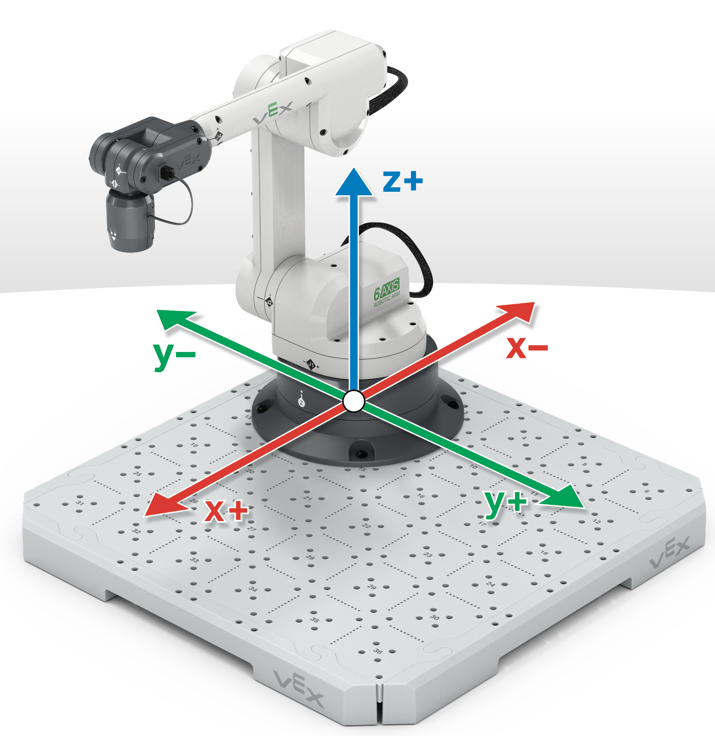
The x-axis can be demonstrated by moving the 6-Axis Arm toward the base (retracted) and away from the base (extended), as shown in this animation.
The y-axis can be demonstrated by moving the 6-Axis Arm to the left and right of the base, as shown in this animation.
The z-axis can be demonstrated by moving the 6-Axis Arm down towards the Tile then up away from the Tile, as shown in this animation.
Estimating Coordinates
The (x, y, z) coordinate is determined by the distance from the (0, 0, 0) coordinate, also called the origin, to the end of the 6-Axis Arm, called the Tool Center Point (TCP).
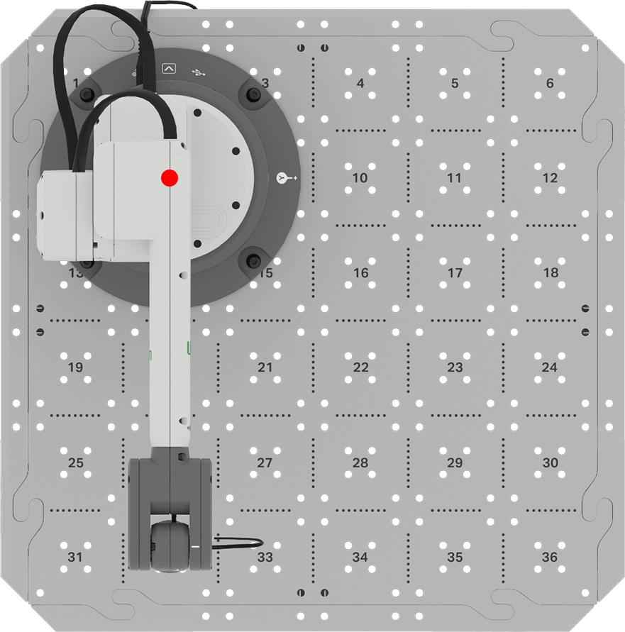
The origin or (0, 0, 0) is the location that all values start from. The (0, 0, 0) on the 6-Axis Arm is located at the center of the base.
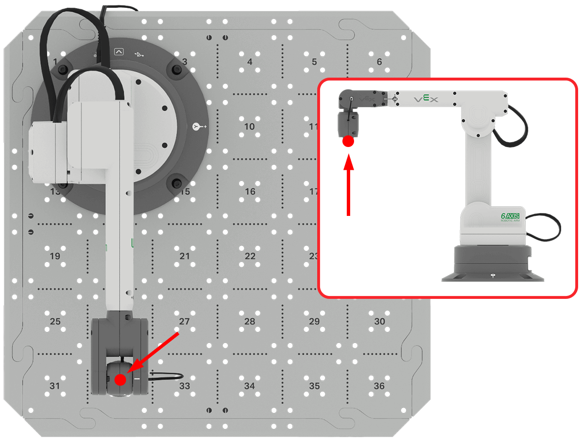
The end of the 6-Axis Arm is known as the Tool Center Point (TCP).
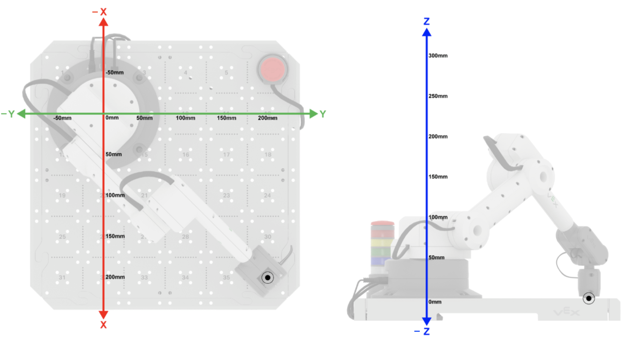
For the 6-Axis Arm in this image, the TCP is at the end of the Magnet Pickup Tool.
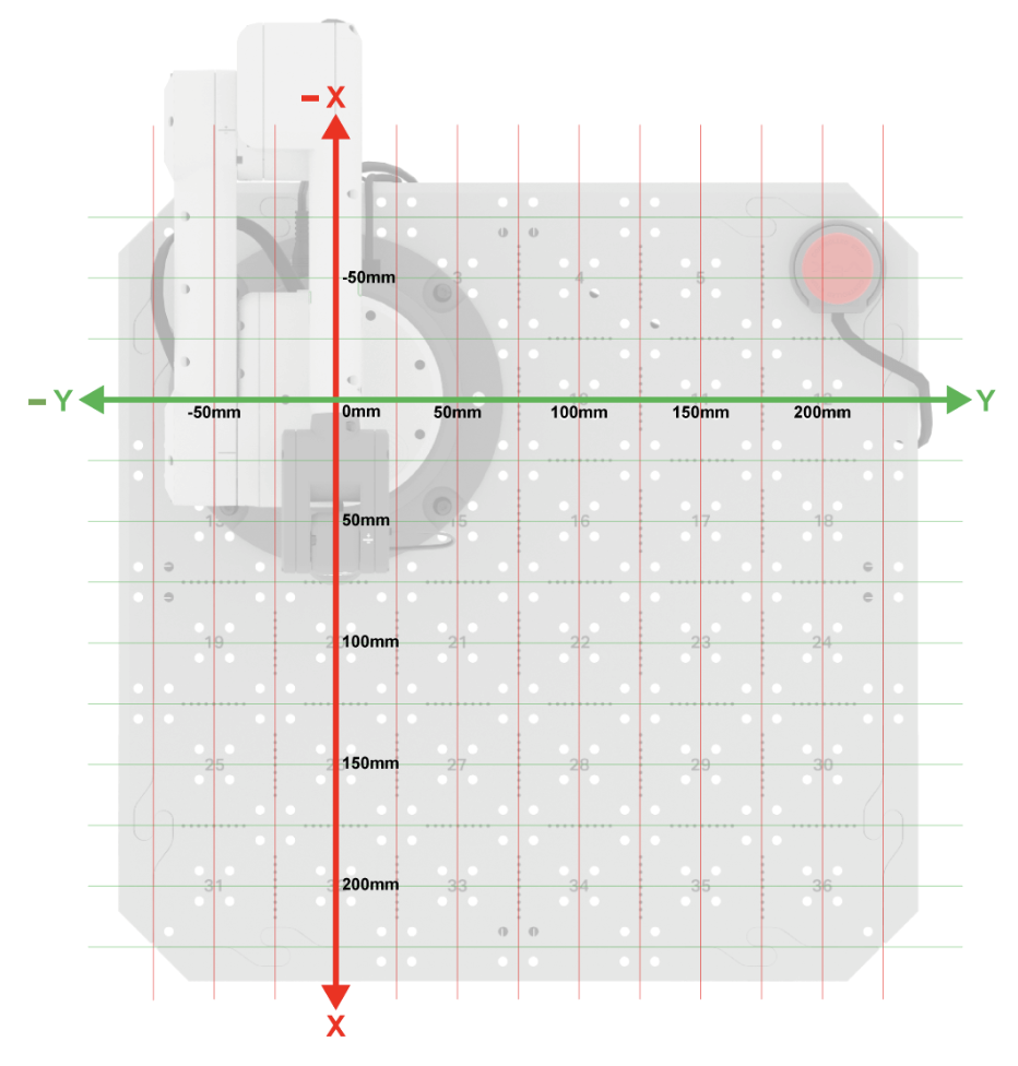
You can use the image here to help determine the x, y-coordinates of the 6-Axis Arm. The z-axis will be shown in a following grid.
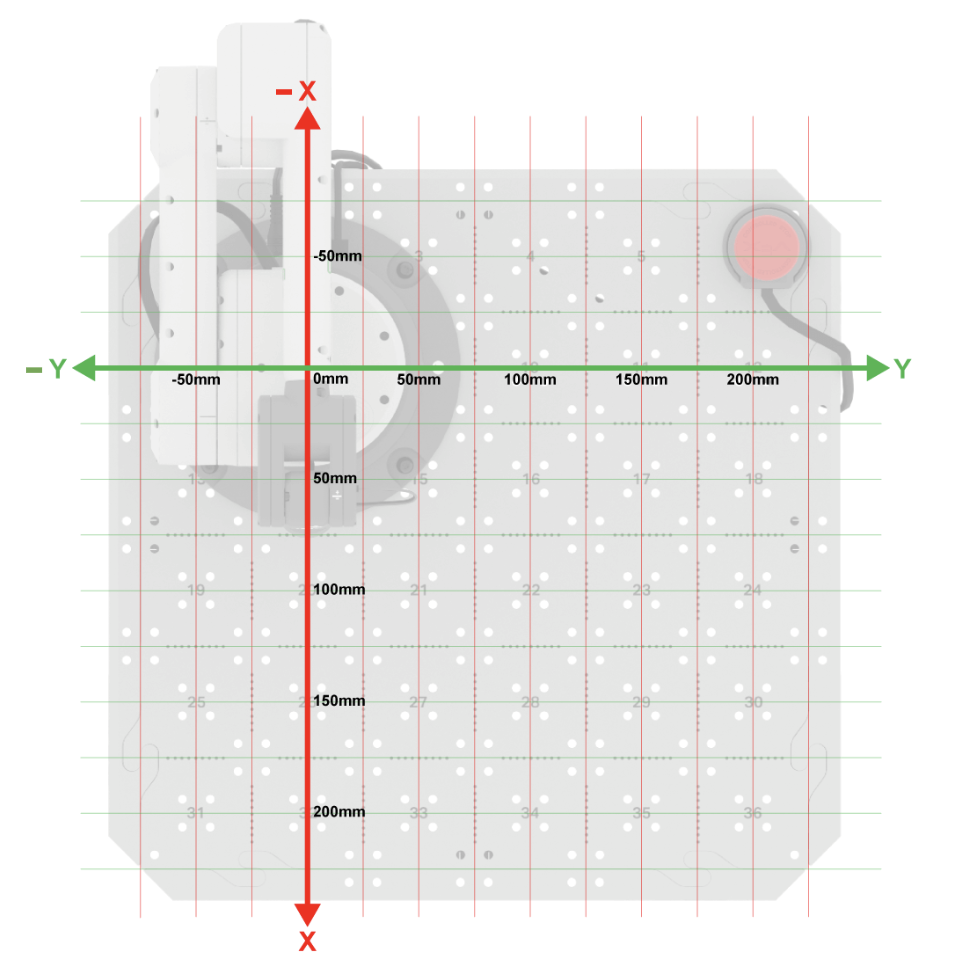
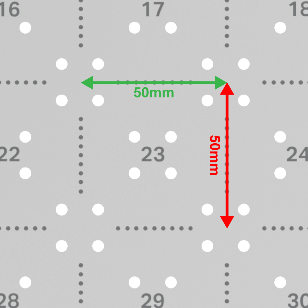
The measurement of each of the individual squares on the Tile is 50mm by 50mm.
Gathering the z-axis value can be done by determining the distance from the Tile to the TCP.
In this example, the z-value of the TCP can be estimated to be just under 200mm using the coordinate grid.

The (x, y, z) coordinate is determined by the distance (in millimeters) from the origin to the TCP along all three axes.
In this example, the (x, y, z) coordinate would be (200, 200, 0) because the TCP is 200mm from the origin in the x-axis, 200 mm from the origin in the y-axis, and 0 mm from the origin in the z-axis.
Activity
Previously in this Lesson, we discussed the Cartesian coordinate system and how to determine coordinates based on the distance from the origin to the TCP. In this activity, you will determine the coordinates of three Tile locations.
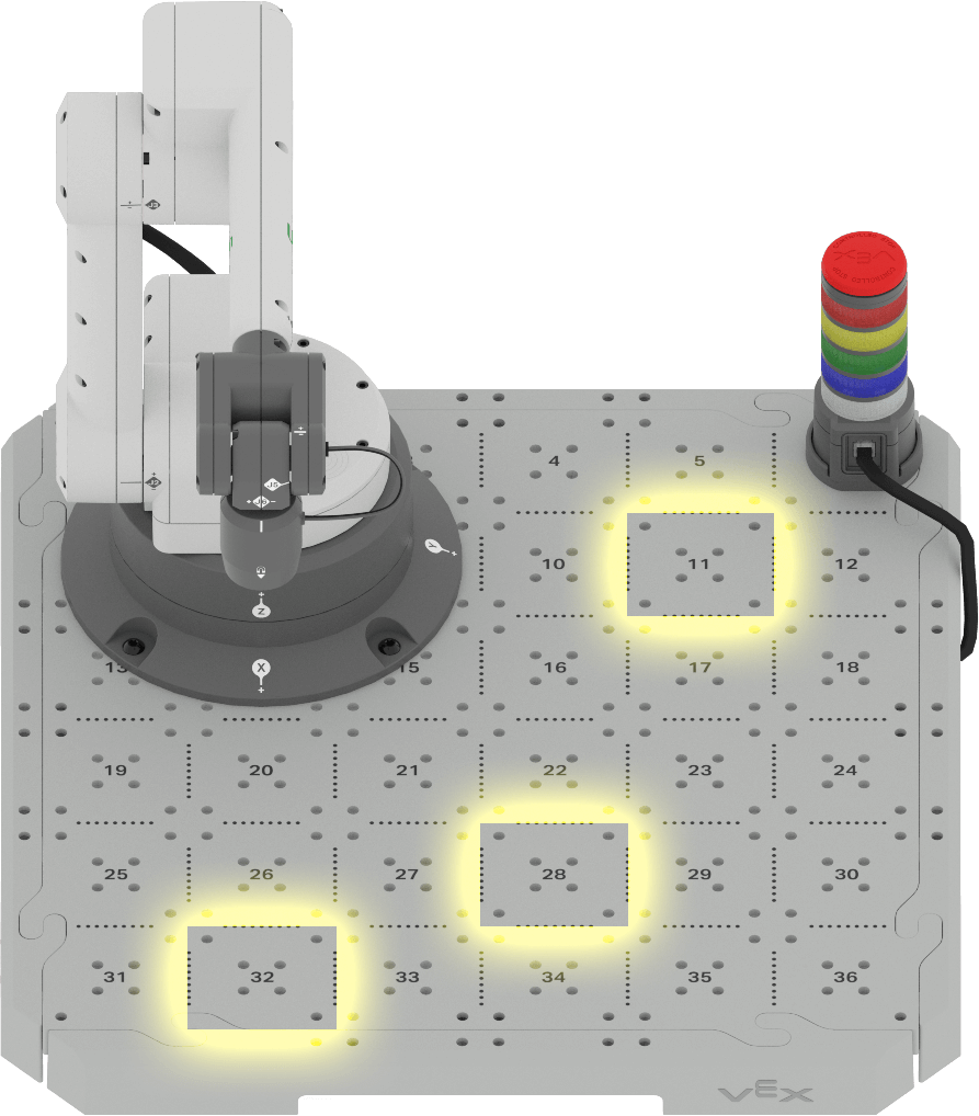
- Estimate the (x, y, z) coordinates of the following Tile locations. Assume that the 6-Axis Arm is touching each Tile location and the z-coordinate is 0 mm.
- Tile location 11
- Tile location 32
- Tile location 28
- Record these coordinates in your engineering notebook. Explain how you determined each coordinate.
Check Your Understanding
Before beginning the next Lesson, ensure that you understand the concepts covered in this Lesson by answering the questions in the document below in your engineering notebook.
Check Your Understanding questions > (Google Doc / .docx / .pdf)
Select Next > to learn how to gather coordinates using the manual movements.