
Previously, you learned about conveyors and diverters, and how they enable efficient transportation of materials in industrial settings. You also learned about how the conveyors on the CTE Workcell function. Now you are ready to begin coding the conveyors to transport Disks. In this Lesson, you will learn:
- How to configure individual conveyor motors in VEXcode.
- How to create a VEXcode project to move Disks from one conveyor to another using time-based movements.
By the end of this Lesson, you will build a project to transport a Disk all the way from the Entry Conveyor, through the Transport Conveyor and onto the Exit Conveyor.

Getting Ready to Code the Conveyors
Before you can code the conveyors on the CTE Workcell, there are some important tasks you must complete to get ready. You will need to configure each individual conveyor motor in VEXcode. You will also need to modify the stack of blocks that initiate a controlled stop, to be sure all of the conveyor motors are included.
Configuring Individual Motors in VEXcode
Each conveyor on the CTE Workcell is controlled by a separate motor. Because of this, you will need to add each motor to the configuration in VEXcode before you can begin your project. Additionally, you will need to be sure each motor is named correctly, and that it is set up to spin in the direction needed to successfully transport materials.
Configuring the Entry Conveyor Motor
Open the Brain CTE 6-Axis Arm Base Template project.
Note: For a reminder on how to open Examples in VEXcode EXP, refer to the previous Unit.
Rename the project to Unit 4 Lesson 2 and save it to your device.

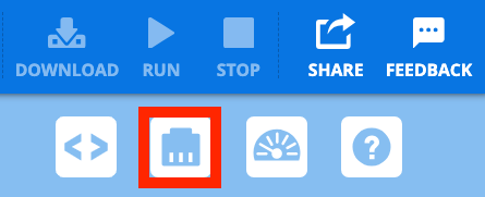
Open the Devices Window.
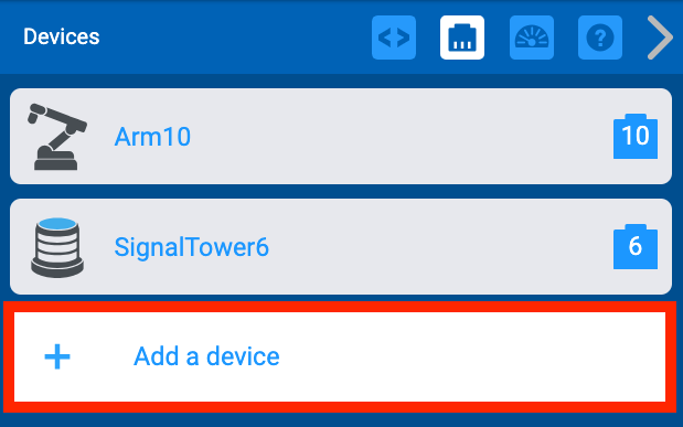
Select Add a Device.
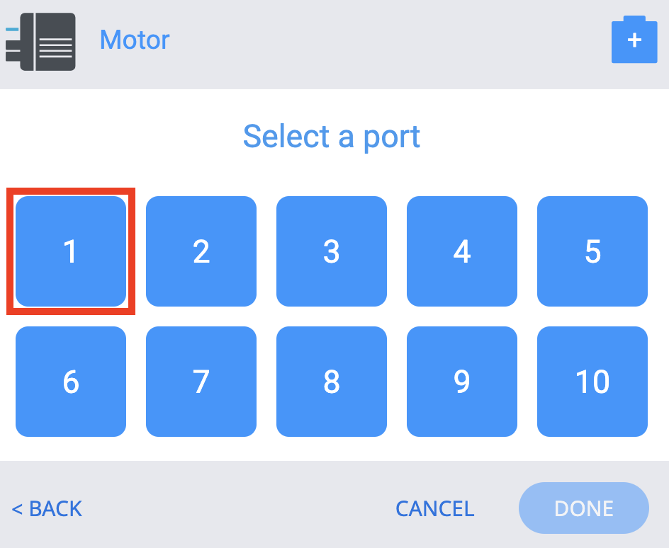
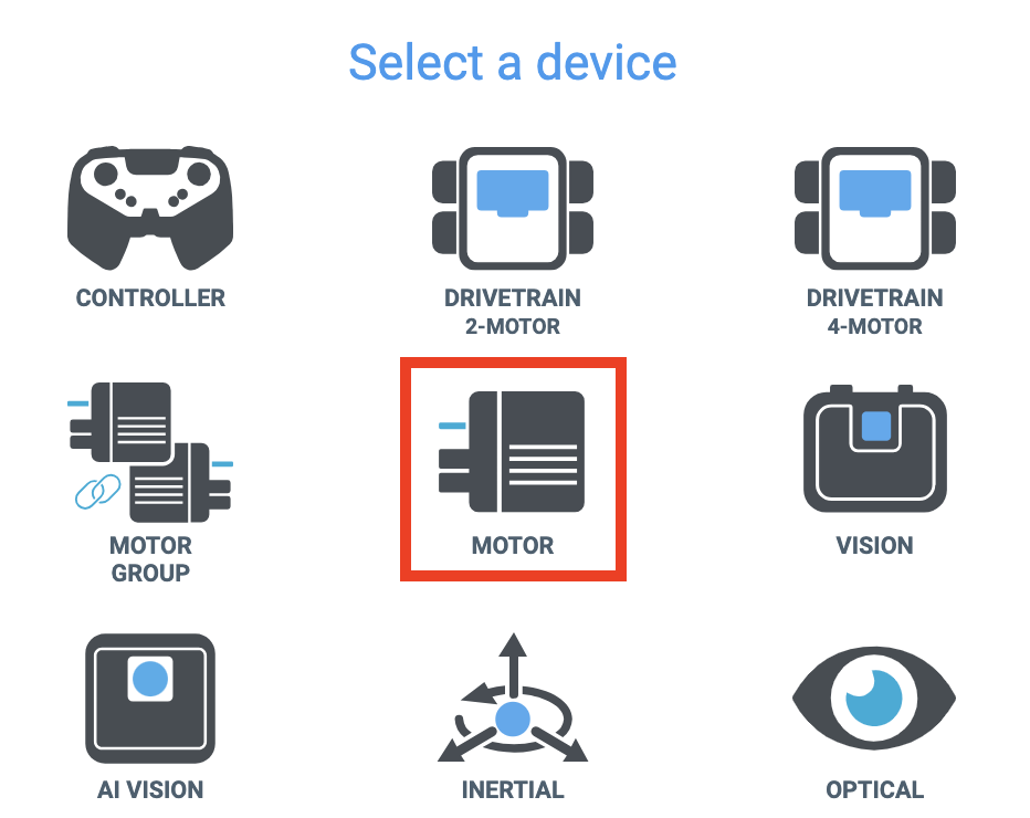
Select Motor from the list of Devices.

Select port 1 on the Brain to match the port the Entry Conveyor Motor is plugged into.
Note: Be sure the Entry Conveyor Motor is plugged into port 1 on the Brain.
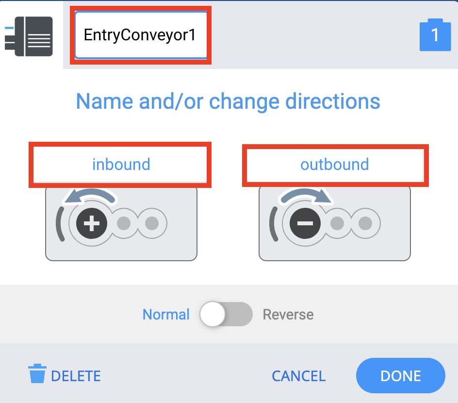
Edit the labels to match this image.
- The motor should be renamed to clearly identify it as the Entry Conveyor motor. The number in the name references the port it is plugged into.
- The directions of the motor should also be renamed to inbound and outbound, as the default forward and reverse labels do not adequately describe the movement of the conveyors.
Inbound means the Entry Conveyor is spinning towards the Transport Conveyor. Outbound means the Entry Conveyor is spinning away from the Transport Conveyor.
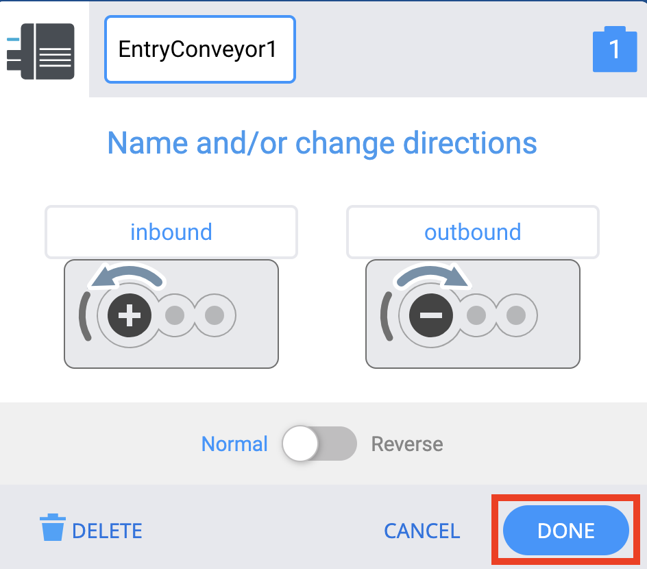
Select Done.
Configuring the Exit Conveyor Motor
The Exit Conveyor Motor can be configured in the same way as the Entry Conveyor Motor.
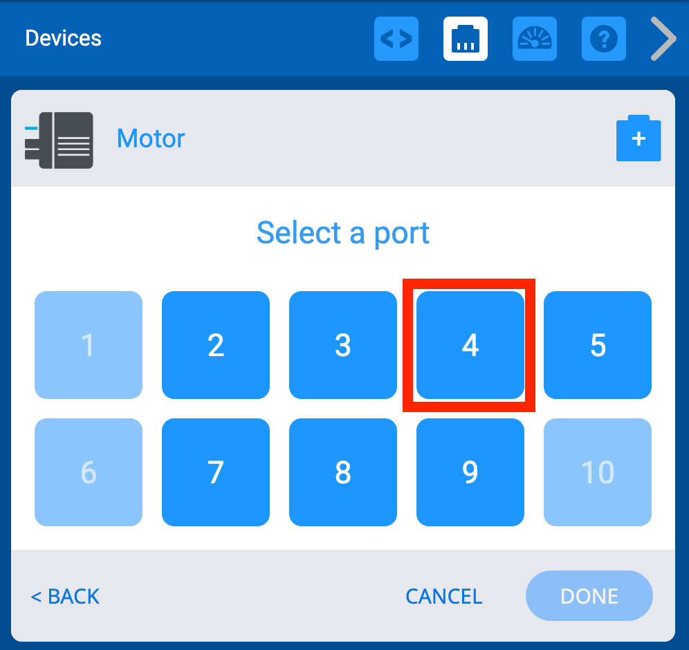
In the Devices Window, select Motor from the list of devices.

Select port 4 to match the port the Exit Conveyor motor is plugged into.
Note: Be sure the Exit Conveyor motor is plugged into port 4 on the Brain.
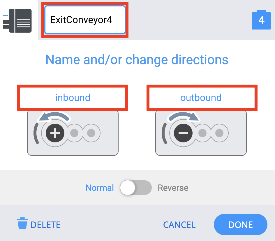
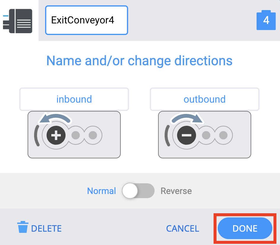
Edit the labels to match those in the image.
- The motor should be renamed to clearly identify it as the Exit Conveyor motor. The number in the name references the port it is plugged into.
- The directions of the motor should also be renamed to inbound and outbound, as you did previously for the Entry Conveyor.
Inbound means the Exit Conveyor is spinning towards the Transport Conveyor. Outbound means the Exit Conveyor is spinning away from the Transport Conveyor.
Select Done.
Configuring the Transport Conveyor Motor
Finally, you will need to configure the Transport Conveyor motor. In addition, you will need to reverse the direction of the motor for the conveyor to move in the needed direction.
In the Devices Window, select Motor from the list of Devices.
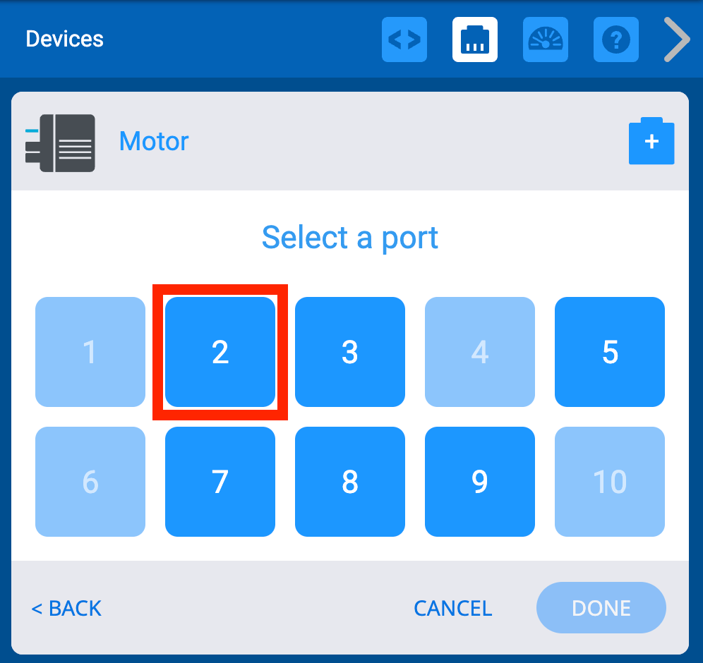
Select port 2 to match the port the Transport Conveyor motor is plugged into.
Note: Be sure that the Transport Conveyor motor is plugged into port 2 on the Brain.
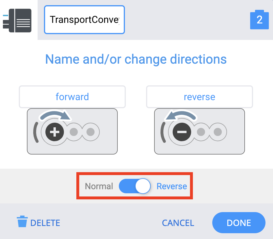
Rename the motor to TransportConveyor2.
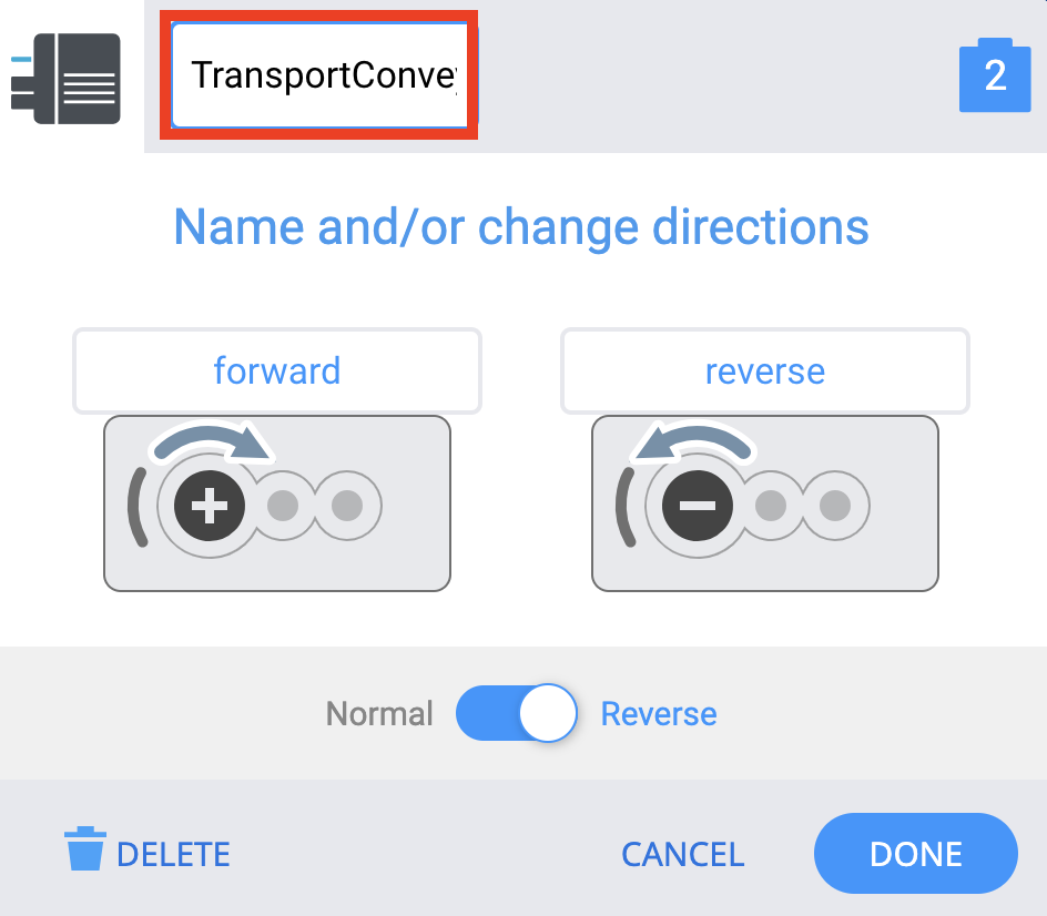
In order for the Transport Conveyor to move materials in the correct directions, you will need to select the toggle button to change the motor direction from Normal to Reverse.
Transport Conveyor Motor Direction
While configuring the Transport Conveyor motor, you had to reverse its direction. This is because the motor will spin the Transport Conveyor clockwise by default. You can determine the default spin direction of a motor based on the label of the motor.
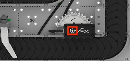
On the top of each motor, there is an icon indicating which direction is positive. In the case of the Transport Conveyor, the arrow is pointing clockwise. This means that by default, any Disk placed on the Transport Conveyor would spin from the Entry Conveyor to the first diverter. By reversing the motor in the configuration, you ensure that the forward direction matches what is discussed as the correct path along the conveyor.
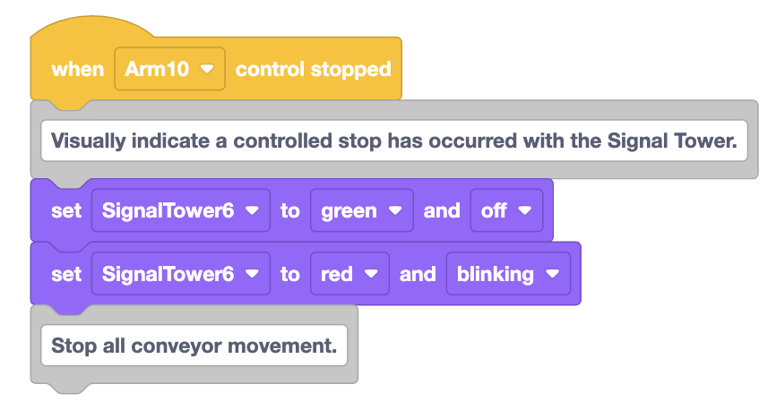
Modifying the Controlled Stop
Now that you have configured all of the conveyor motors, you need to update the controlled stop. When a controlled stop is triggered, all motors should stop running, so that you can be sure the CTE Workcell Base is safe to move around. You are going to add blocks to the When controlled stop hat block to stop these conveyor motors.
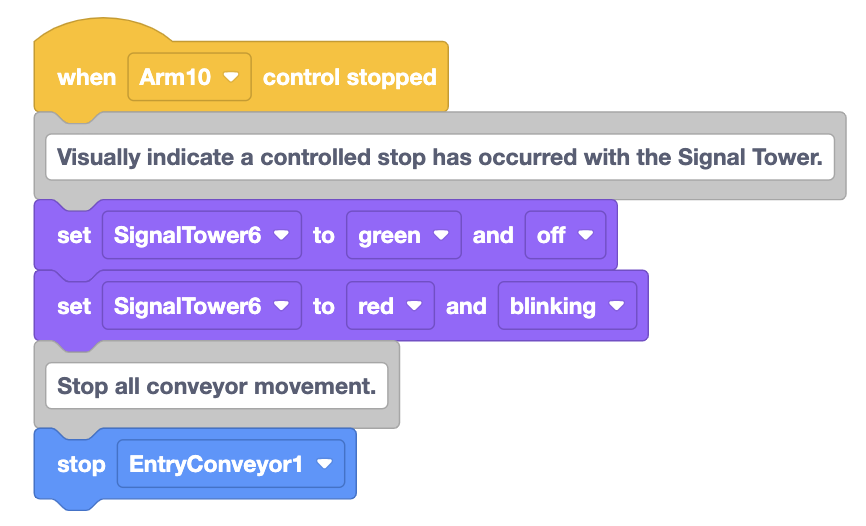
Create a Comment to describe the conveyor behaviors needed during a controlled stop.
Add the Comment block to the existing stack of blocks.
Drag out a Stop motor block to stop the Entry Conveyor, and attach it to the stack of blocks.
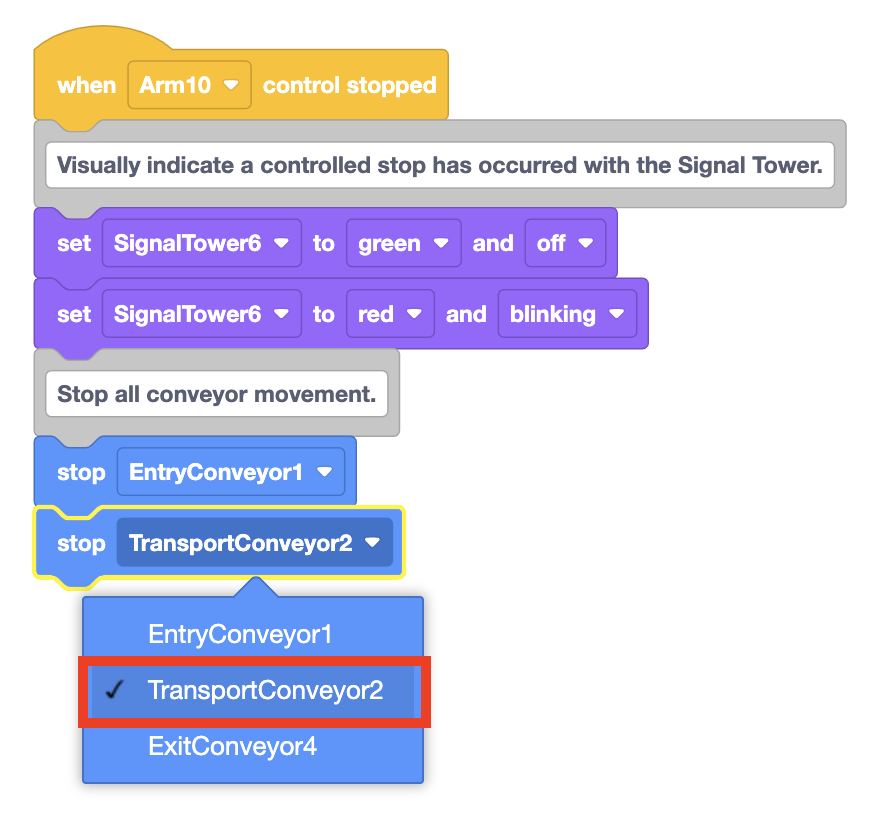
Drag out another Stop motor block and attach it to the bottom of the stack of blocks.
Select the arrow to open the drop down menu and select 'TransportConveyor2' to set the parameter to stop the Transport Conveyor in a controlled stop.
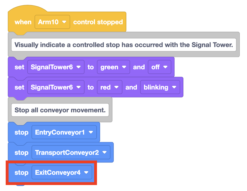
Add a third Stop motor block to the stack. Change the parameter to 'ExitConveyor4'.
Creating a Project to Transport a Disk Using the Conveyors
Now that you have configured your conveyor motors and modified the controlled stop, you can begin to build a project to transport a Disk using the conveyors. You will begin to build a project for the Disk to travel from the Entry Conveyor, along the Transport Conveyor to the Exit Conveyor. To do so, the movement of the Disk along the conveyors must be carefully coordinated. One way to achieve this coordination is to create a project using time-based movements, as shown in the video below.
Time-Based Movements
By using a combination of Wait, Spin, and Stop motor blocks, you can create a project where each conveyor starts and stops at the right time to transfer a Disk from one conveyor to the next. This way of coding the conveyors is referred to as using time-based movements.
Building the Project
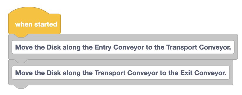
Record the planning steps needed to move the Disk, like those shown in the image here, in your engineering notebook.

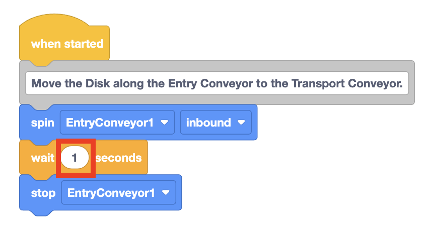
Create Comment blocks for each step of your plan, and attach them to the When started block.
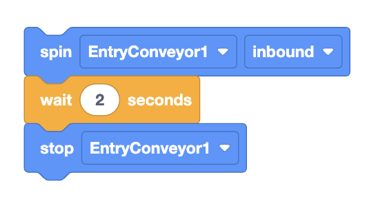
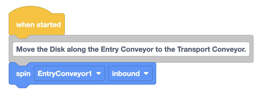
Attach a Spin block beneath the first Comment.
The Disk is starting on the Entry Conveyor and in the direction of the Transport Conveyor, so the parameters can remain set to 'EntryConveyor1' and 'inbound'.
The Spin block will spin the motor forever until it is told to stop the motor.
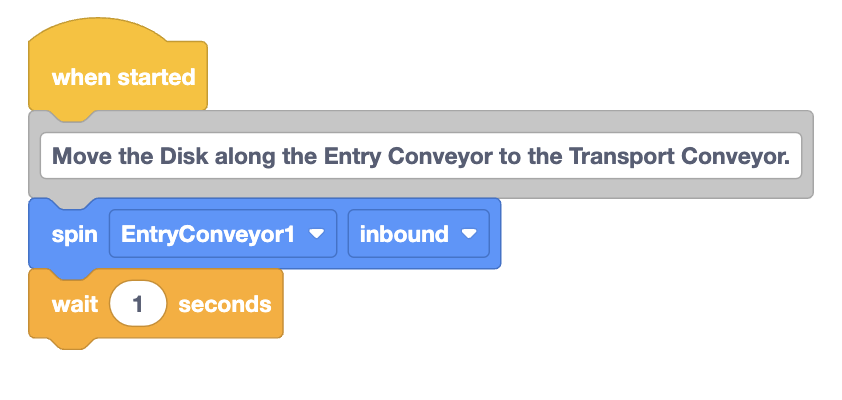
Next, attach a Wait block.
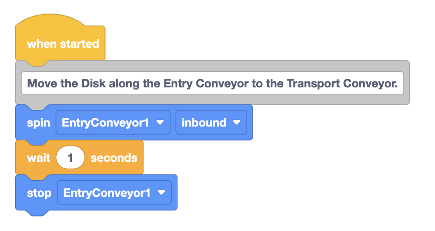
Attach a Stop motor block to the bottom of the stack of blocks. Be sure that the parameter is set as 'EntryConveyor1'.
Make a prediction about what you think will happen when the project is run. Record it in your engineering notebook.
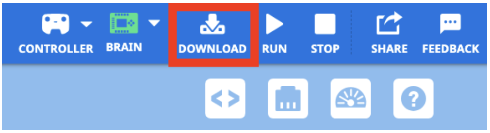
Be sure the Brain is connected to VEXcode, and download the project to the Brain.
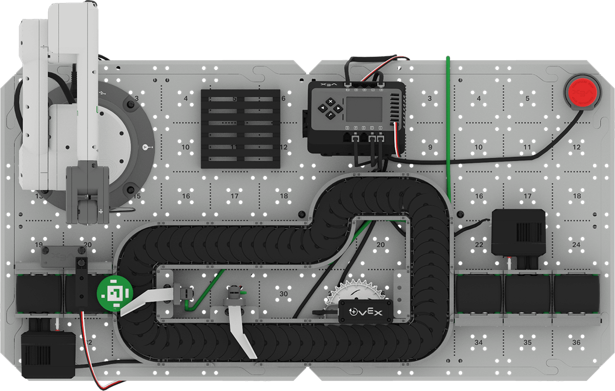
Be sure a green Disk is placed on the start of the Entry Conveyor, as shown here. Press the Check button on the Brain to run the project to test it.
Observe the behaviors of conveyor. Does it transport the Disk to the end of the Entry Conveyor? Why or why not?

When the conveyor has stopped moving, press the X button on the Brain to stop the project. Record your observations in your engineering notebook.

Timing the Conveyor
When you ran your project, you probably noticed that the Entry Conveyor did not move the Disk all the way to the Transport Conveyor. This is because the parameter in the Wait block is only set to 1 second. More time is needed for the Entry Conveyor to spin, before the Stop motor block is run.
As you build and test a project using time-based movements, you may need to adjust the parameter in the Wait block more than once to achieve the correct timing.
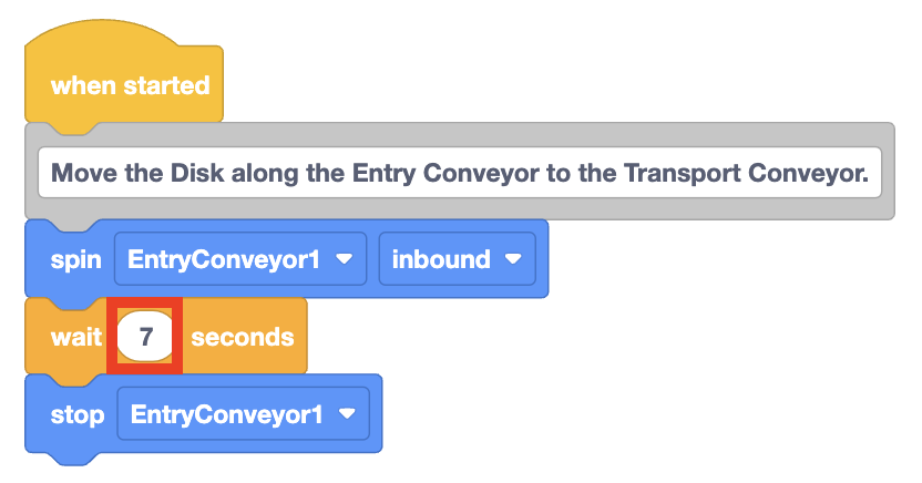
Adjust the parameter in the Wait block to 7 seconds, and download and run the project again to test.
Did the Entry Conveyor transport the Disk all the way to the end, where it could be picked up by the Transport Conveyor? If not, adjust the parameter again until it does.
Note: The number of seconds needed in the parameter may vary. Use numbers that reliably work for your CTE Workcell Base.
Add the blocks needed to move the Disk along the Transport Conveyor.
Note that these are the same blocks as used for the Entry Conveyor, just with the parameters set to 'TransportConveyor2' and 'forward'.
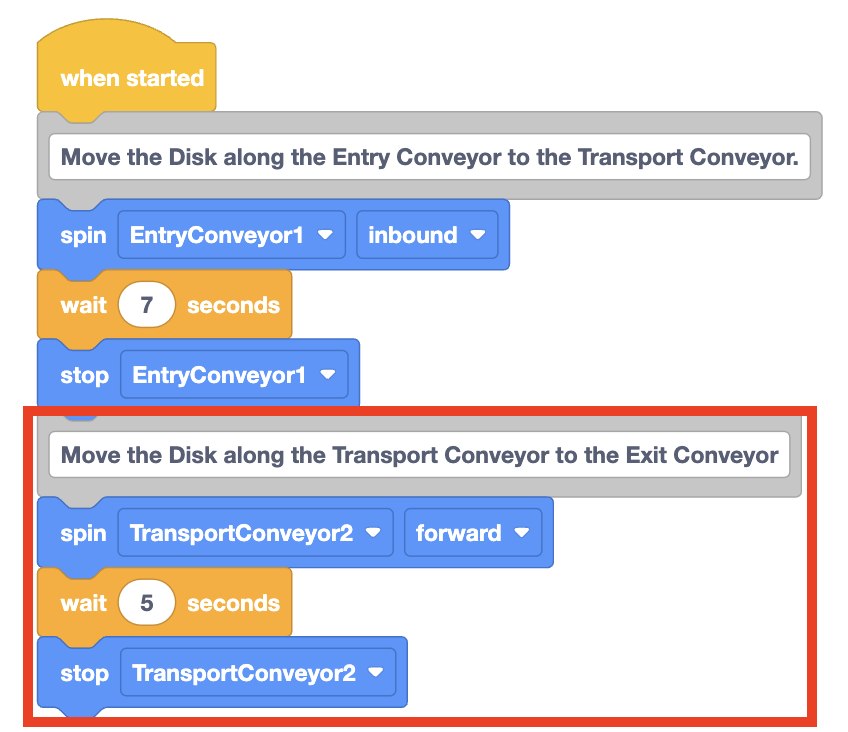
Download the project to the Brain, and run it to test. Does the Disk travel along the length of the Transport Conveyor, stopping at the diverter? If not, adjust the parameter of the Wait block until it does.
For Your Information
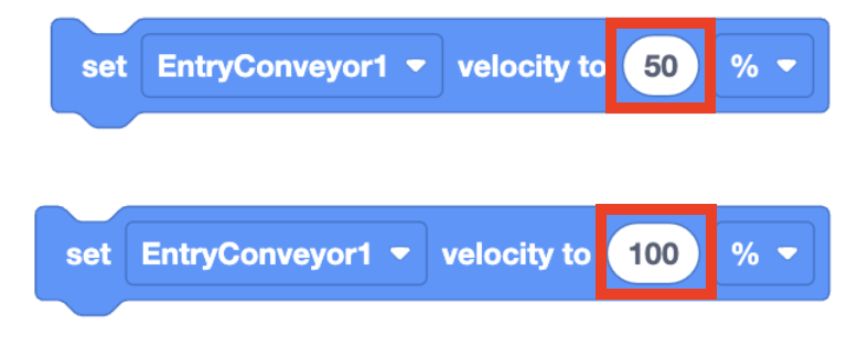
The speed at which objects travel along a conveyor can be modified using the Set motor velocity block. The parameter in the block can be changed to cause the conveyor to spin more quickly, or more slowly. The default conveyor velocity is 50%, and the maximum velocity is 100%.
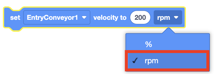
The Set motor velocity block parameter can also be set using rpm's, or rotations per minute.
Activity
Now that you have used time-based movements to code the conveyors to move a Disk from the Entry Conveyor and along the Transport Conveyor to the Exit Conveyor, you will build on to your project to move the Disk to the end of the Exit Conveyor without falling off the end of the conveyor.
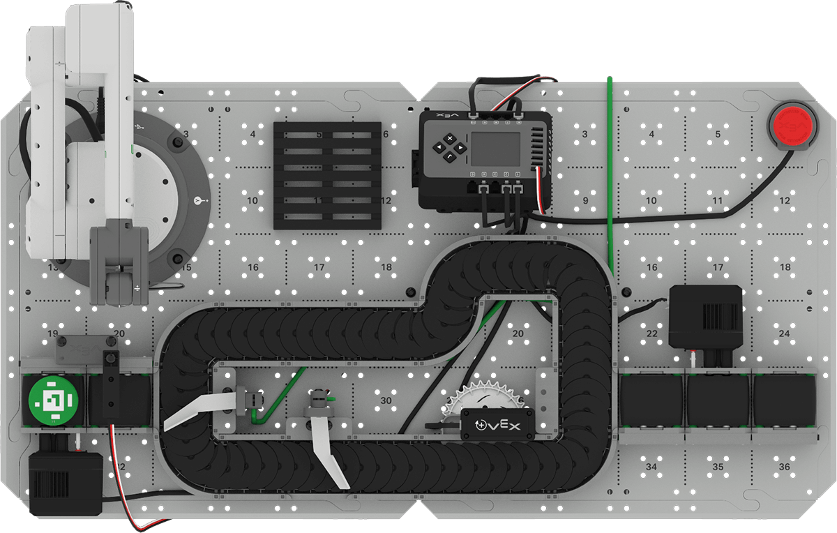
Setup: Place a Disk at the beginning of the Entry Conveyor as shown below.
Activity: Create a VEXcode project that will transport a Disk from the Entry Conveyor, along the Transport Conveyor, to the end of the Exit Conveyor.
- Plan how you will build onto your project to move the Disk to the end of the Exit Conveyor.
- Document your plan in your engineering notebook.
- Rename your project Unit 4 Lesson 2 Activity and save it to your device before you begin editing the project.
- Edit the project in VEXcode to match the plan your group agreed upon.
- Place a Disk on the Entry Conveyor starting point and run the project. Do the conveyors move the Disk to the end of the Exit Conveyor without falling off? Stop the project when the conveyors have finished moving, and record your observations in your engineering notebook.
- If the Disk falls off the end of the Exit Conveyor, edit your project until a Disk travels to the end of the conveyor without falling off. Document any changes in your engineering notebook.
Check Your Understanding
Before moving on to the next Lesson, ensure that you understand the concepts in this Lesson by answering the following questions in your engineering notebook.
Check Your Understanding questions > ( Google Doc / .docx / .pdf )
Select Next > to move on to the Mid Unit Reflection.